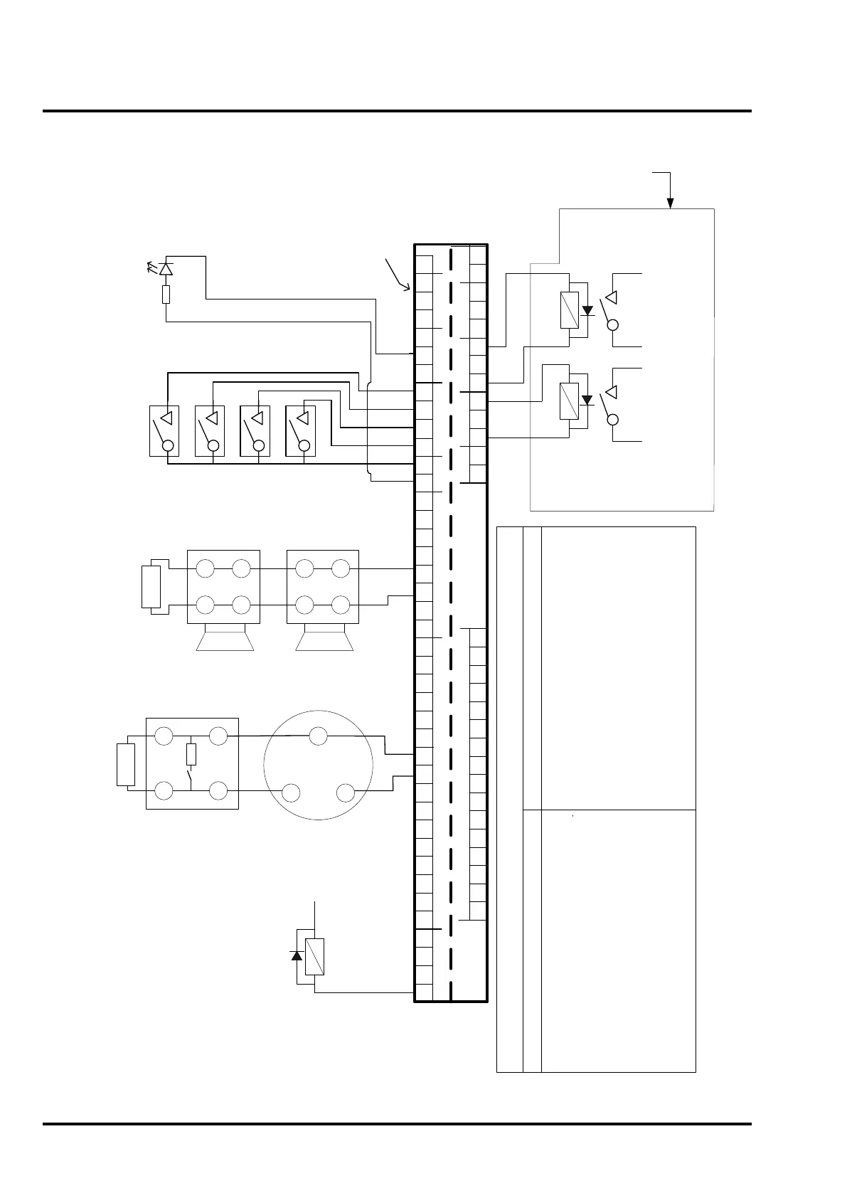
Zonal O/Ps
1 2 3 4
Zone Circuits
Zone Circuits
Alarm Circuits
Aux DC
Inputs
Outputs
A B
Lower
terminal tier
Upper
terminal tier
Lower
terminal tier
Upper
terminal tier
Fault Routing
Aux DC Fire Routing Fire Protection
N/C
RST
GND
Repeater
BActEvacDisC/CRSTEvacSil
0V
24V4 -4 +3 +2 +1 + 3 -2 -1 -8 -8 +7 -6 -5 -4 -3 -2 -1 -1 + 2 + 3 + 4 + 5 + 6 + 7 +
RST
N/OPO/-PC/+O/-PC/+
C/-PO/+
0V
24V9 + 10 + 11 + 12 + 13 + 14 + 15 + 16 + 16 -9 - 10 - 11 - 12 - 13 - 14 - 15 -
+
-
+
-
+
-
+
10k end-of-line resistor
Manual call point
with 90R resistor
1 2
1A 2A
Typical Zone Wiring
3k9 end-of-line resistor
-
-
+
+
-
-
+
+
Typical Alarm Circuit Wiring
Typical Input Circuit Wiring
for Remote Silence, Evac,
Reset & Class Change
Typical remote
output wiring
Repeater Wiring - see
Figure 1 - Repeater
connection diagram
Connect to
Aux
24VDC
24VDC
relay
Typical zonal
output wiring
Field relay Requirements:
Coil resistance – 2k6 to 4k5 Ohms
Voltage 24VDC Nom
[min 18V, max 30V]
Fitted with suppression diode as shown.
Relay local to
fire indicating
equipment
Relay local to
fault indicating
equipment
[Normally
Energised]
Fire and Fault output
wiring shown for the
monitored/powered
configuration
For Fire and Fire Protection O/Ps:
Quiescent: 2VDC [open circuit voltage]
Active [fire]: 24V – [nom]
For Fault O/P:
Quiescent: 24VDC [nom]
Active [fault]: 2VDC [open circuit voltage]
Connections:
Observe correct polarity.
[+ = Positive, - = Negative]
Fire Routing, Fault Routing and Fire Protection O/P configuration - Output specification:
When configured as monitored/powered outputs:
For Fire and Fire Protection O/Ps:
Volt free relay contacts shown in quiescent [de-energised]
condition.
For Fault O/P:
Volt free relay contacts shown in healthy [energised]
condition.
Connections:
Connect to normally open or normally closed contact as
required. [P= Pole, C= Closed, O= Open]
Applied voltage must not exceed 30VDC.
When configured as volt-free changeover relays:
Terminal identification notes:
C/C = Class Change.
B Act = Buzzer Active
RST = Reset
[Normally open switch contacts]
Remote
indicating
equipment
2k2 0.5W
resistor
 Loading...

