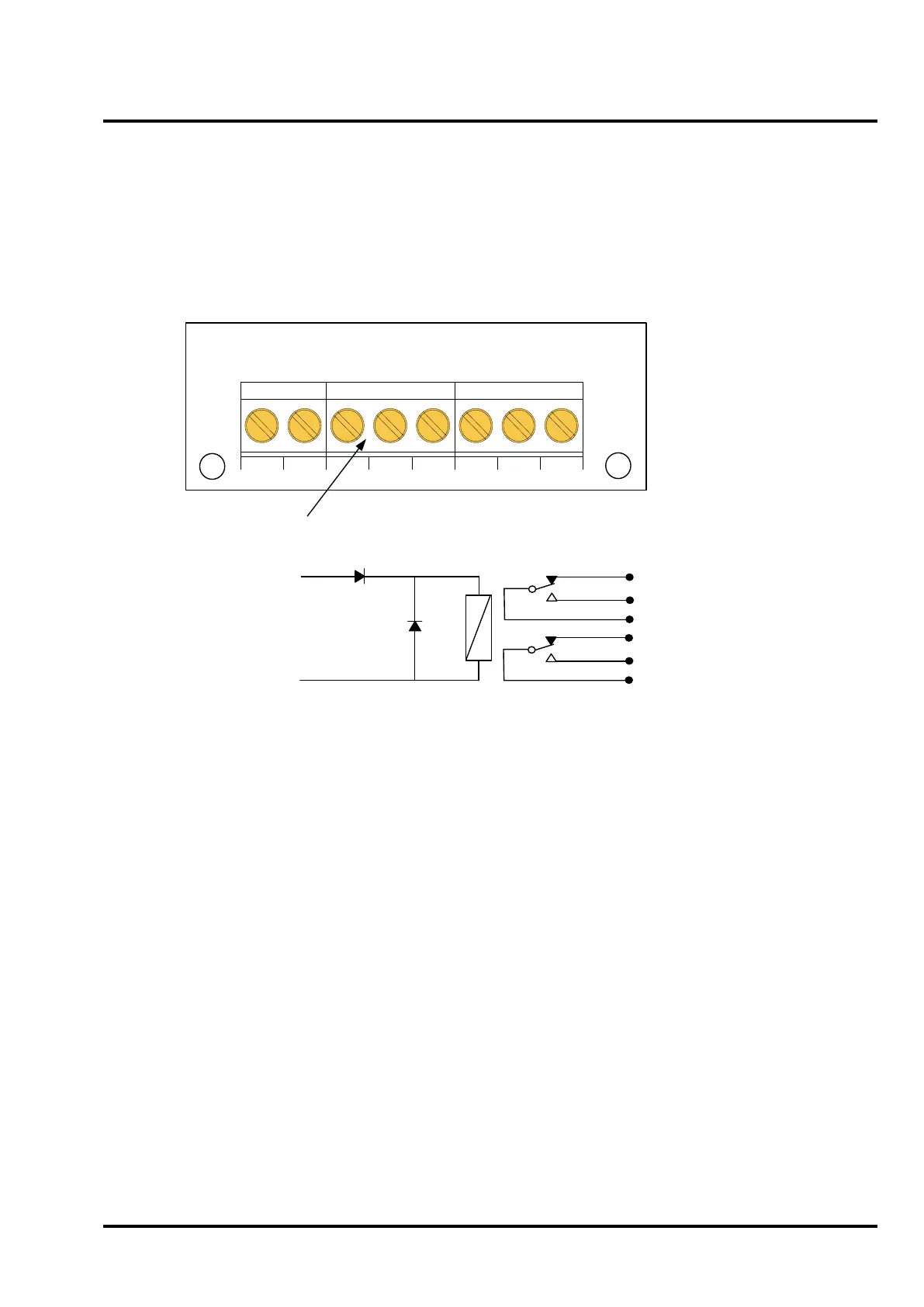
Terminal block
Terminals
Max conductor: 2.5mm.
24V, 0V: Relay coil connections – observe polarity.
P1: Relay contact 1 pole.
N/C: Relay contact 1 normally closed.
N/O: Relay contact 1 normally open.
P2: Relay contact 2 pole.
N/C: Relay contact 2 normally closed.
N/O: Relay contact 2 normally open.
Ratings
Coil: Operating voltage range: 17.5Vdc to 30Vdc.
Operating current: 8mA at 24Vdc.
Resistance: 2900Ω.
Relay contacts: 2A at 30Vdc.
Warning – Do not exceed the rated voltage or
current.
PCB Layout
24V 0V P1
N/C N/O
P2
N/C N/O
CEL A1466 Iss 2
28/1/93
Dimensions
Board size: 30mm x 45mm.
Height: 15mm.
Fixing centres: 24mm x 30mm.
Fixing hole sizes: M4 clearance.
Installation
Must be installed within enclosure of
the equipment being controlled.
Environmental: Clean, dry location
not subject to excessive vibration or
shock.
Temperature: -10 to +70 deg C.
24Vdc
0Vdc
TB1
N/C
N/O
P1
N/C
N/O
P2
TB2
TB3
Circuit Diagram
Specification
TB1 TB2 TB3
 Loading...

