T1200
MARINEC-P-A
3 02/14
PAGE 24 of 67
10. C1714 Voyage Data Recorder Interface Module
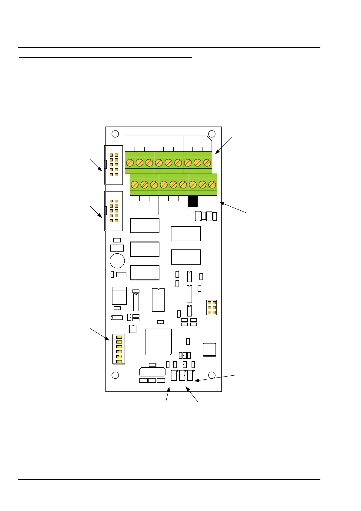
Figure 12 illustrates the C1714 VDR Interface Module fitted in the T1216-C and T1232-C.
Figure 12 – C1714 VDR Interface Module
SW1
RL4
P
GFIRE
FIRE
M.S.
GFLT
BFLT
MFLT
RL5
RL3
RL2
RL1
6
1
J1
SW2
Interface Board
J3
FLT
FLT
COMMS PROC
PS
RESET
PROC FAULT
PN-2
SP2
SP1
PN-8
PN-4
PN-1
Voyage Data Recorder
C1
J2
FIRE
M. SPACE
C P O C P O
B
A
Tx-
FAULT
O
MAINS
FAULT
C
C
P
O
O
P
C
ON
BDM and
Programming
Connector
GENERAL
BATTERY
FAULT
GENERAL
FIRE
Tx+
U2
U8
RL5
TB3
C16
R7
X1
U3
C10
+
C1
C2
C3
C4
C5
C6
C7
C9
C11
C12
C15
D1
J2
R10
R11
R13
R1
R2
R3
R4
R5
R14
R15
R16
RN1
U1
U5
U6
U4
L3L2
L1
ON
1 2 3 4 5 6
RL1
RL3
RL4
C13
C14
R9
R6
R12
U7
J3
TB2
C8
C17
R8
TS1
TS2
RL2
Ribbon Connection
from Panel
motherboard
Ribbon Connection
to additional
Output Boards
Configuration DIL switches.
PN-1 to PN-8 select the
panel number from 1 to 15.
SP1 & SP2 are spare and
not currently used.
Volt-free Relay outputs to VDR.
Fault Relays are normally
energised.
C=Normally Closed
O=Normally Open
P=Pole
Contacts rated at 1A 30Vdc
maximum
Serial data output
to VDR
PS ON LED
Indicates power
supply is connected
PROC FLT LED
Indicates
microcontroller has
failed
COMMS FLT LED
Indicates communication
with the panel
motherboard has failed
10.1 C1714 VDR Interface Module Description
The C1714 VDR Interface Module provides outputs for connection to a ship’s Voyage Data Recorder to allow
recording of various panel events. Volt-free relay contacts are provided along with a RS422 serial port which
conforms to IEC 61162-1. The serial data output conforms to IEC PAS 61162-102 – Extra Requirements for the
Voyage Data Recorder.
 Loading...

