T1200
MARINEC-P-A
3 02/14
PAGE 38 of 67
14.5.1 T1200 Power Supply Features and Connections
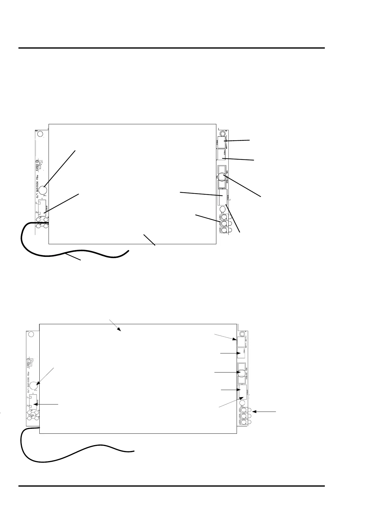
Figure 16 shows the layout of the PS40-1-09 24Vdc Power Supply used in the T1204 panel.
See Figure 17 for the layout of the PS136-1-09 4 Amp 110/230Vac power supply used in the T1216-C and
T1232-C panels.
Figure 16 – PS40-1-09 1.5 Amp 24Volt DC Power Supply Layout
Incoming 24Vdc
supply fuse (F1).
Non-replaceable
Incoming 24Vdc
supply terminals
Earth Lead
PSU Cover.
DO NOT
REMOVE
DC Load
Connector
[+ve & -ve]
LEDs:
Supply On (green)
Charger Fault (yellow)
Battery Fault (yellow)
Battery
Connections
(Batt+, Batt-)
Thermistor
Connections
Fault O/Ps:
Incoming Supply
Fail
Common Fault
Battery Fuse
(F6)
Type: T8AH250V
Figure 17 – PS136-1-09 4 Amp 110/230Vac Power Supply Layout
Protective Cover.
DO NOT REMOVE
Battery Connections
(Batt+, Batt-)
Thermistor Connections
Battery Fuse (F6)
Type: T8AH250V
Load Connections
(+ve, -ve)
Fault Outputs:
Incoming Supply Fail
Common Fault
LEDs:
Supply On (green)
Charger Fault (yellow)
Battery Fault (yellow)
Earth Lead
AC Mains supply fuse (F1)
Non-replaceable
AC Mains supply
terminals
 Loading...

