‐5‐
E
F
X
Y
Z
N
O
9
6
3
#
C
B
A
T
U
V
J
K
L
8
5
P
Q
R
G
H
I
7
4
S
2
1
0
*
W
M
D
Manufactured in the UK by
REN 1.0
Receiver Frequency 169.48125MHz
Complies with:
ECC/DEC/(05 )02
ETSI EN 300 220-2 Class 1
a1
b2
c3
d4
e5
f6
g7
h8
No user serviceable parts inside case.
8
5
2
0
*
1
4
7
#
3
6
9
tynetec
DO NOT
UNPLUG
OR
SWITCH OFF
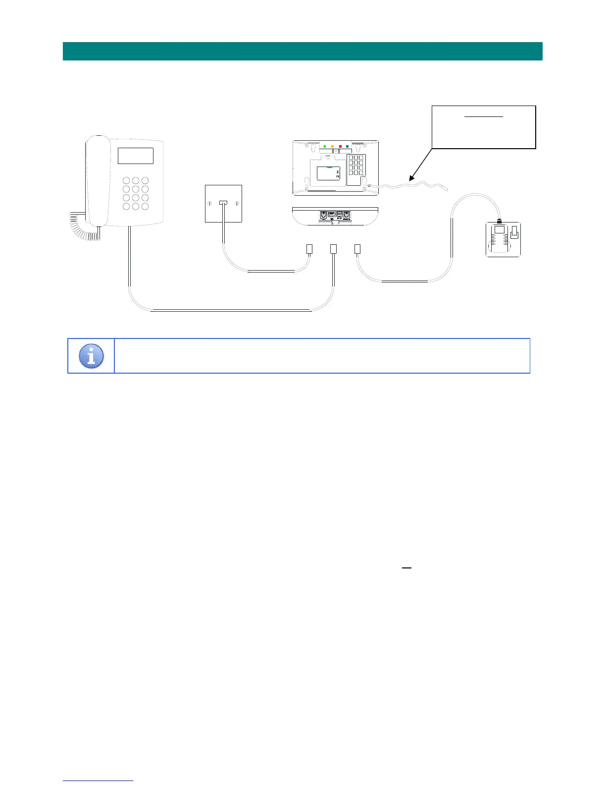
1.4CONNECTINGTHEREACHA
‐HOMEALARM
TheReachAt‐Homealarmunitshouldonlybeinstalledandprogrammedbytrainedpersonnel.
BasicConnections…
TheReachwillusuallybetablemountedwithin3metresofamainssupplyandthemastertelephone
socket.Ifextensioncablesareusedcareshouldbetakentoensurethatnoonecantripovertheleads.
InstallationProcedure…
1.UnplugtheusersTelephonefromtheBTwallsocketandplugitintotheReachTELsocket.Ifthe
userhasaDECTcordlesstelephone,extensiontelephonesocketsinotherroomsorBroadbandsee
sections1.1,1.5and1.6formoreinformation.
2.ConnecttheTelecomLeadbetweentheReachC/OsocketandtheBTwallsocket(wherethe
userstelephonewasoriginallypluggedin).
3.ConnectthePowerLeadbetweentheReachSUPPLYsocketandthemainssupply.
4.TheDATAsocketisonlyusedforfirmwareupgradesorfortheconnectionofhardwiredinputs
suchasceilingpullcords,seesection2.3.3formoredetails.
5.Choosetheconnectorcoveriftheunitisbeingplacedflatonthetableorthestandifitisbeing
placedintheuprightposition.Itcanalsobewallmountedusingthekeyholesontherear.Atemplate
isprovidedonthecartonflaptomarkthewallbeforedrilling(wallplugsandscrewsnotincluded).
6.Routetheleadsthroughthecover(orstand)andfixwiththesinglescrewprovided.
7.Theflexibleaerialwireoutthesideoftheunitreceivessignalsfromradiodevicesandmustnotbe
cut‐downinlengthorcoiled‐up.
8.TheTouchpendantispre‐learned,anyadditionalpendantsorotherradiodevicesshouldbelearned
andtestedasdescribedinsections2.5and2.6.
9.Performatestcalltothecontrolcentretoverifycorrectinstallationandprogramming.
MAINS
ELECTRICITY
BTWALL
SOCKET
TELEPHONE
POWERLEAD
TELECOM LEAD
Reach
AT‐HOMEALARMUNIT
C/O TEL SUPPLY
IMPORTANT
Thisaerialwirereceivessignals
fromradiodevicesandmust
notbecut‐downorcoiled‐up