MAX-7 / NEO-7 / LEA-7 - Hardware Integration Manual
GPS.G7-HW-11006-1 Hardware description
Page 13 of 55
2.6.3 Display Data Channel (DDC)
An I
2
C compatible Display Data Channel (DDC) interface is available with u-blox 7 modules for serial
communication with an external host CPU. The interface only supports operation in slave mode (master mode is
not supported). The DDC protocol and electrical interface are fully compatible with the Fast-Mode of the I
2
C
industry standard. DDC pins SDA and SCL have internal pull-up resistors.
For more information about the DDC implementation, see the u-blox 7 Receiver Description Including Protocol
Specification [4]
. For bandwidth information see the Data Sheet. For timing, parameters consult the I
2
C standard
[9].
The u-blox 7 DDC interface supports serial communication with u-blox wireless modules. See the
specification of the applicable wireless module to confirm compatibility.
With u-blox 7, when reading the DDC internal register at address 0xFF (messages transmit buffer), the
master must not set the reading address before every byte is accessed, as this could cause a faulty
behavior. After every byte is read from register 0xFF the internal address counter is incremented by one,
saturating at 0xFF. Therefore, subsequent reads can be performed continuously.
2.6.4 SPI (NEO-7)
With NEO-7 modules, an SPI interface is available for communication to a host CPU.
SPI is not available in the default configuration, because its pins are shared with the UART and DDC
interfaces. The SPI interface can be enabled by connecting D_SEL to ground (NEO-7) (see section 2.7.3).
For speed and clock frequency see the Data Sheet.
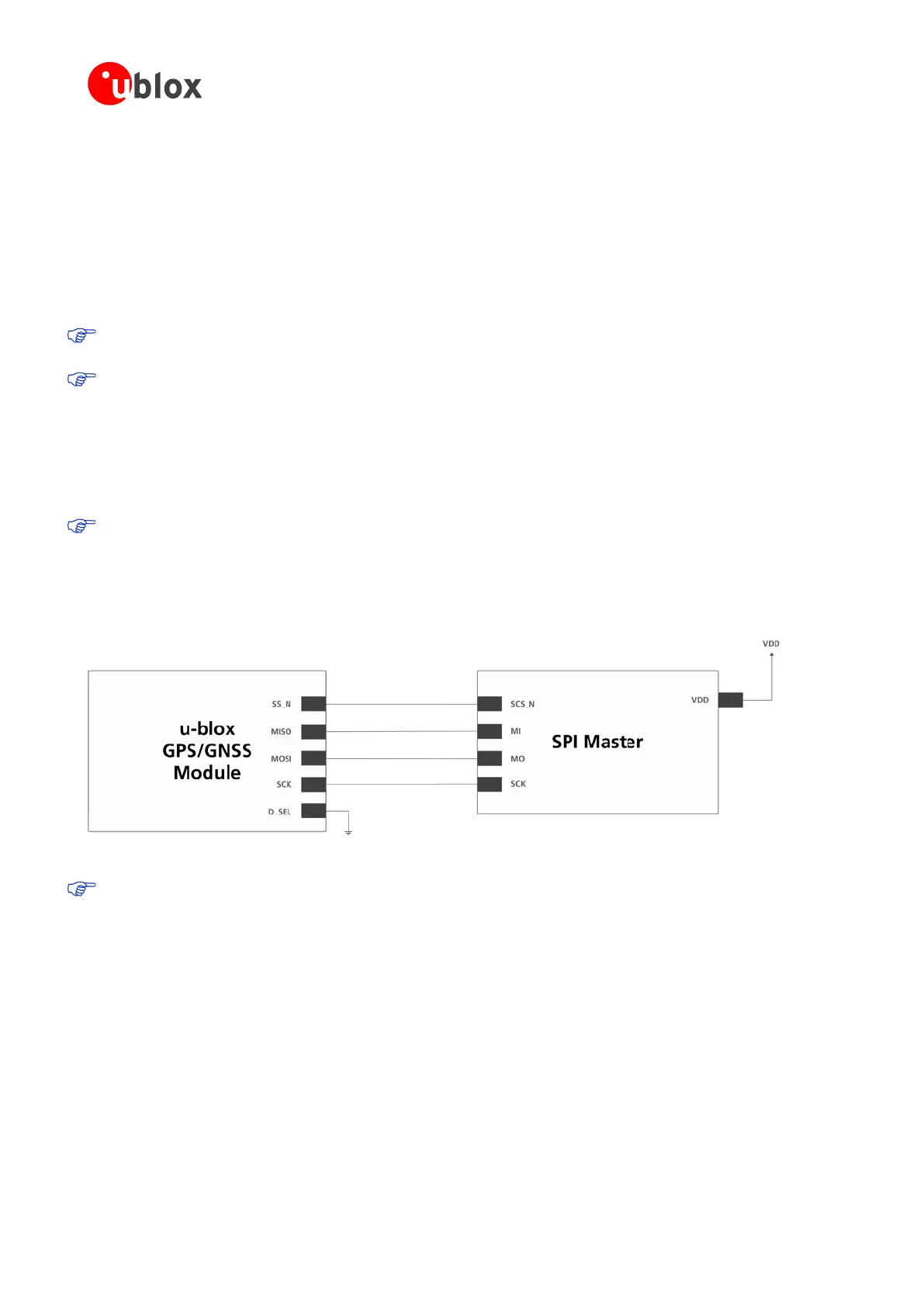
Figure 4 shows how to connect a u-blox GPS/GNSS receiver to a host/master. The signal on the pins must meet
the conditions specified in the Data Sheet.
Figure 4: Connecting to SPI Master
VCC_IO must have the same voltage level as the host.
2.7 I/O pins
2.7.1 RESET_N: Reset input
Driving RESET_N low activates a hardware reset of the system. Use this pin only to reset the module. Do not use
RESET_N to turn the module on and off, since the reset state increases power consumption. With u-blox 7
RESET_N is an input only.
2.7.2 EXTINT: External interrupt
EXTINT is an external interrupt pin with fixed input voltage thresholds with respect to VCC or VCC_IO (see the
data sheet for more information). It can be used for wake-up functions in Power Save Mode on all u-blox 7
modules and for aiding. Leave open if unused.

 Loading...
