MAX-7 / NEO-7 / LEA-7 - Hardware Integration Manual
GPS.G7-HW-11006-1 Product handling
Page 48 of 55
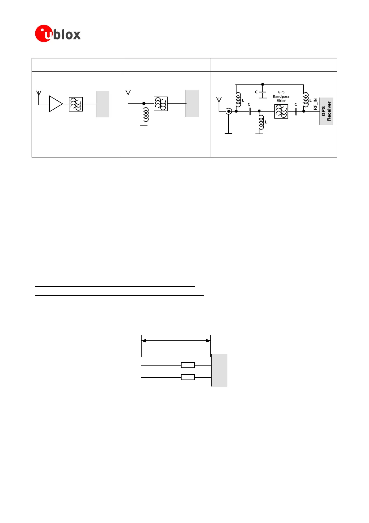
Small passive antennas (<2 dBic and
performance critical)
Passive antennas (>2 dBic or
performance sufficient)
Active antennas (without internal filter which need the
module antenna supervisor circuits)
D
RF_IN
GPS
Receiver
LNA
GPS
Bandpass
Filtler
E
RF_IN
GPS
Receiver
L
GPS
Bandpass
Filtler
F
LNA with appropriate ESD rating and
maximum input power
GPS Band pass Filter: SAW or Ceramic
with low insertion loss and appropriate
ESD rating
Figure 36: EOS and ESD Precautions
5.3.6 Electromagnetic interference (EMI)
Electromagnetic interference (EMI) is the addition or coupling of energy originating from any RF emitting device.
This can cause a spontaneous reset of the GPS/GNSS receiver or result in unstable performance. Any unshielded
line or segment (>3mm) connected to the GPS/GNSS receiver can effectively act as antenna and lead to EMI
disturbances or damage.
The following elements are critical regarding EMI:
• Unshielded connectors (e.g. pin rows etc.)
• Weakly shielded lines on PCB (e.g. on top or bottom layer and especially at the border of a PCB)
• Weak GND concept (e.g. small and/or long ground line connections)
EMI protection measures are recommended when RF emitting devices are near the GPS/GNSS receiver. To
minimize the effect of EMI a robust grounding concept is essential. To achieve electromagnetic robustness follow
the standard EMI suppression techniques.
http://www.murata.com/products/emc/knowhow/index.html
http://www.murata.com/products/emc/knowhow/pdf/4to5e.pdf
Improved EMI protection can be achieved by inserting a resistor (e.g. R>20 Ω) or better yet a ferrite bead
(BLM15HD102SN1) or an inductor (LQG15HS47NJ02) into any unshielded PCB lines connected to the GPS/GNSS
receiver. Place the resistor as close as possible to the GPS/GNSS receiver pin.
Example of EMI protection measures on the RX/TX line using a ferrite bead:
TX
RX
GPS
Receiver
FB
FB
BLM15HD102SN1
>10mm
Figure 37: EMI Precautions
VCC can be protected using a feed thru capacitor. For electromagnetic compatibility (EMC) of the RF_IN pin,
refer to section 5.3.5

 Loading...
