MAX-7 / NEO-7 / LEA-7 - Hardware Integration Manual
GPS.G7-HW-11006-1 Product handling
Page 47 of 55
• When soldering RF connectors and patch antennas to the receiver’s
RF pin, make sure to use an ESD safe soldering iron (tip).
Failure to observe these precautions can result in severe damage to the GPS/GNSS module!
5.3.3 ESD protection measures
GPS/GNSS positioning modules are sensitive to Electrostatic Discharge (ESD). Special
precautions are required when handling.
For more robust designs, employ additional ESD protection measures. Using an LNA with appropriate
ESD rating can provide enhanced GPS/GNSS performance with passive antennas and increases ESD
protection.
Most defects caused by ESD can be prevented by following strict ESD protection rules for production and
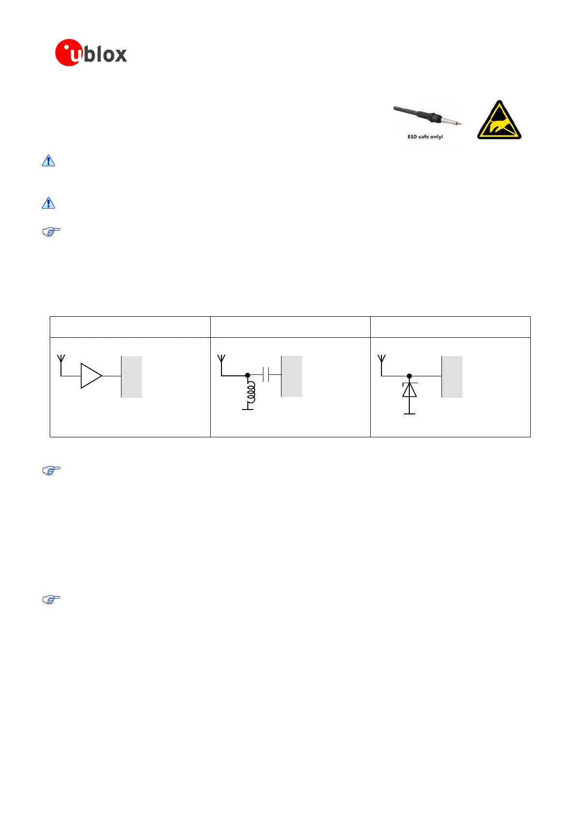
handling. When implementing passive antenna patches or external antenna connection points, then additional
ESD measures as shown in Figure 35 can also avoid failures in the field.
Small passive antennas (<2 dBic and
performance critical)
Passive antennas (>2 dBic or performance
sufficient)
Active antennas
A
B
C
LNA with appropriate ESD rating
Figure 35: ESD Precautions
Protection measure A is preferred because it offers the best GPS performance and best level of ESD
protection.
5.3.4 Electrical Overstress (EOS)
Electrical Overstress (EOS) usually describes situations when the maximum input power exceeds the maximum
specified ratings. EOS failure can happen if RF emitters are close to a GPS/GNSS receiver or its antenna. EOS
causes damage to the chip structures. If the RF_IN is damaged by EOS, it is hard to determine whether the chip
structures have been damaged by ESD or EOS.
5.3.5 EOS protection measures
For designs with GPS/GNSS positioning modules and wireless (e.g. GSM/GPRS) transceivers in close
proximity, ensure sufficient isolation between the wireless and GPS antennas. If wireless power output
causes the specified maximum power input at the GPS RF_IN to be exceeded, employ EOS protection
measures to prevent overstress damage.
For robustness, EOS protection measures as shown in Figure 36 are recommended for designs combining
wireless communication transceivers (e.g. GSM, GPRS) and GPS in the same design or in close proximity.

 Loading...
