MAX-7 / NEO-7 / LEA-7 - Hardware Integration Manual
GPS.G7-HW-11006-1 Design
Page 27 of 55
3.4.2 Active antenna design not using antenna supervisor (NEO-7N, NEO-7M,
MAX-7C, MAX-7Q)
Active antennas have an integrated low-noise amplifier. Active antennas require a power supply that will
contribute to the total GPS system power consumption budget with additional 5 to 20 mA typically.
If the supply voltage of the u-blox 7 receiver matches the supply voltage of the antenna (e.g. 3.0 V), use the
filtered supply voltage VCC_RF output to supply the antenna. See section 3.4.2.1. This design is used for
modules MAX-7C, MAX-7Q, NEO-7N, and NEO-7M in combination with active antenna.
In case of different supply voltage, use a filtered external supply as shown in section 3.4.2.2
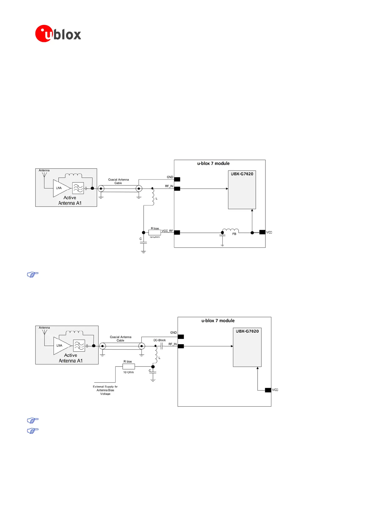
3.4.2.1 Active antenna design, VCC_RF used to supply active antenna
Figure 22 shows an active antenna design supplied by VCC_RF.
Figure 22: Active antenna design, external supply from VCC_RF (for exact pin orientation see data sheet)
For recomended parts, see section 3.5.
3.4.2.2 Active antenna design powered from external supply
Figure 23 shows a design with direct externally powered active antenna.
This circuit works with all u-blox 7 modules, also with modules without VCC_RF output.
Figure 23: Active antenna design, direct external supply (for exact pin orientation see data sheet)
For recomended parts, see section 3.5.
In case VCC_RF voltage does not match with the antenna supply voltage, use a filtered external supply
as shown in Figure 23.

 Loading...
