MAX-7 / NEO-7 / LEA-7 - Hardware Integration Manual
GPS.G7-HW-11006-1 Design
Page 23 of 55
Non 'emitting'
circuits
PCB
Digital & Analog circuits
Non
'emitting'
circuits
Antenna
Digital Part
RF Part
1
2
3
4
5
6
7
8
9
10
11
12
13
14
28
27
26
25
24
23
22
21
20
19
18
17
16
15
RF & heat
'
e
mitting'
circuits
PCB
Digital & Analog circuits
RF
& heat
'
e
mitting'
circuits
Antenna
1
2
3
4
5
6
7
8
9
10
11
12
13
14
28
27
26
25
24
23
22
21
20
19
18
17
16
15
Figure 14: Placement (for exact pin orientation see data sheet)
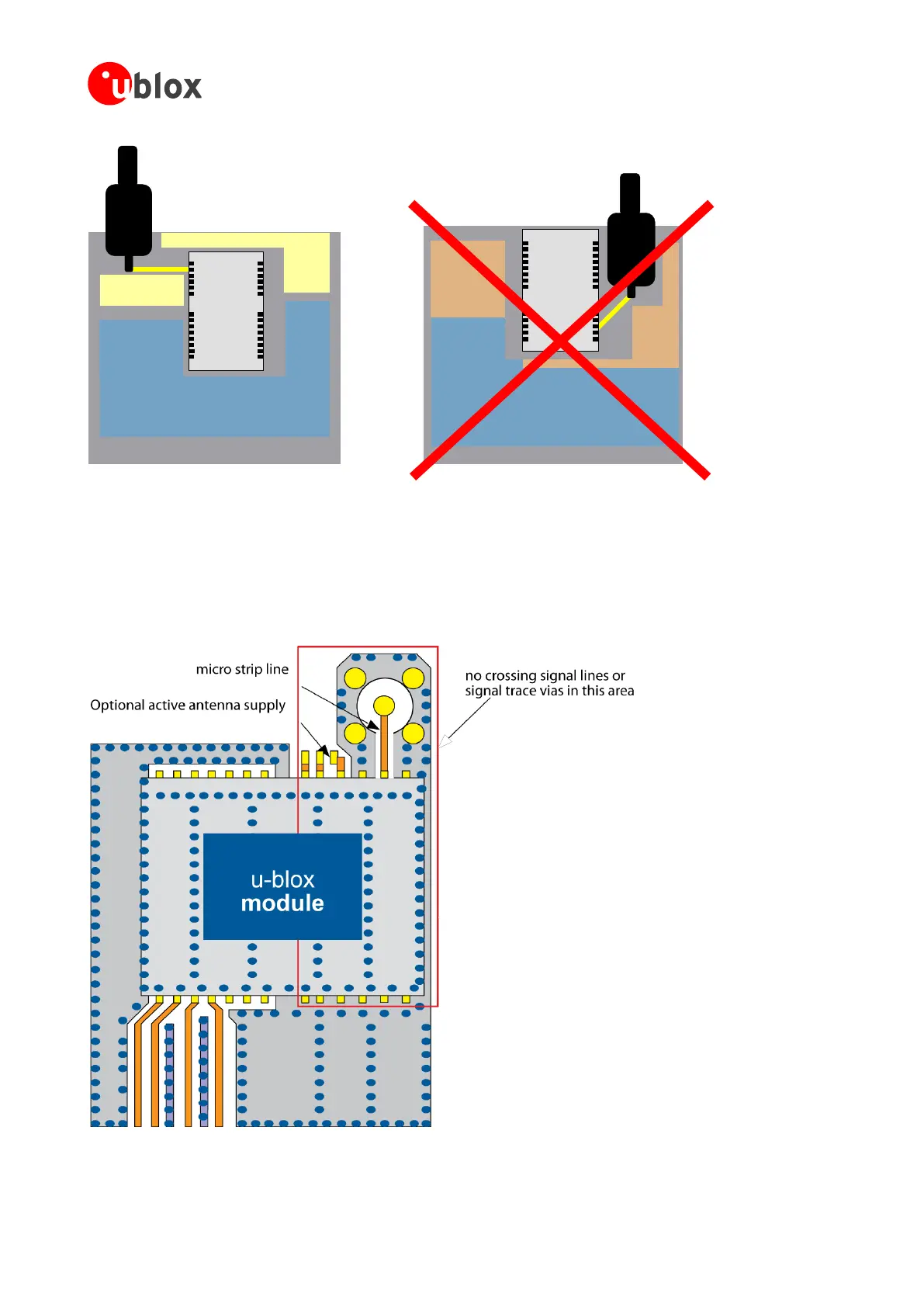
3.3.3 Antenna connection and ground plane design
u-blox 7 modules can be connected to passive or active antennas. The RF connection is on the PCB and connects
the RF_IN pin with the antenna feed point or the signal pin of the connector, respectively. Figure 15 illustrates
connection to a typical five-pin RF connector. One can see the improved shielding for digital lines as discussed in
the GPS Antenna Application Note [6]. Depending on the actual size of the ground area, if possible place
additional vias in the outer region. In particular, terminate the edges of the ground area with a dense line of vias.
Figure 15: Recommended layout (for exact pin orientation see data sheet)

 Loading...
