MAX-7 / NEO-7 / LEA-7 - Hardware Integration Manual
GPS.G7-HW-11006-1 Design
Page 26 of 55
3.4 Antenna and Antenna supervision
3.4.1 Antenna design with passive antenna
A design using a passive antenna requires more attention to the layout of the RF section. Typically, a passive
antenna is located near electronic components; therefore, care should be taken to reduce electrical ‘noise’ that
may interfere with the antenna performance. Passive antennas do not require a DC bias voltage and can be
directly connected to the RF input pin RF_IN. Sometimes, they may also need a passive matching network to
match the impedance to 50 Ω.
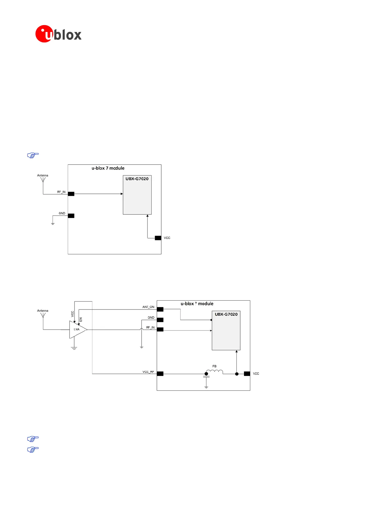
3.4.1.1 Minimal setup with a good patch antenna
Figure 20 shows a minimal setup for a design with a good GPS patch antenna.
NEO-7N is optimized for Immunity to near field Wireless
Figure 20: Module design with passive antenna (for exact pin orientation see data sheet)
3.4.1.2 Setup for best performance with passive antenna
Figure 21 shows a design using an external LNA to increase the sensitivity for best performance with passive
antenna.
Figure 21: Module design with passive antenna and an external LNA (for exact pin orientation see data sheet)
ANT_ON (antenna on) can be used to turn on and off an optional external LNA.
The VCC_RF output can be used to supply the LNA with a filtered supply voltage.
For recomended parts, see section 3.5
A standard GPS LNA has enough bandwidth to amplify GPS and GLONASS signals.

 Loading...
