UBX-G7020 - Hardware Integration Manual
Design-in
GPS.G7-HW-10003 Objective Specification Page 22 of 74
2.2.7 Active Antenna Supervisor
u-blox 7 firmware supports active antenna supervisors. There is either a 2-pin or a 3-pin antenna supervisor. By
default the 2-pin antenna supervisor is enabled. The antenna supervisor pins are located at PIO14, PIO15 and
PIO16.
If the UART is remapped to PIO15 and PIO16, the antenna supervisor cannot be used!
The antenna supervisor gives information about the status of the active antenna and will turn off the supply to
the active antenna in case a short is detected or to optimize the power consumption when in Power Save Mode.
2.2.7.1 2-pin antenna supervisor
The 2-pin antenna supervisor function, which is enabled by default, comprises PIO15 for the ANT_OK input and
PIO16 for the ANT_OFF output.
Antenna OK
“high” = Antenna OK
“low” = Antenna not OK
Polarity can be changed by Low Level
Configuration if the external circuitry requires
other polarity, see section 2.10.2
Control signal to turn on and off the antenna supply
“high” = Antenna OFF
“low” = Antenna ON
Polarity can be changed by Low Level
Configuration if the external circuitry requires
other polarity, see section 2.10.2
Table 6: 2-pin antenna supervisor pins
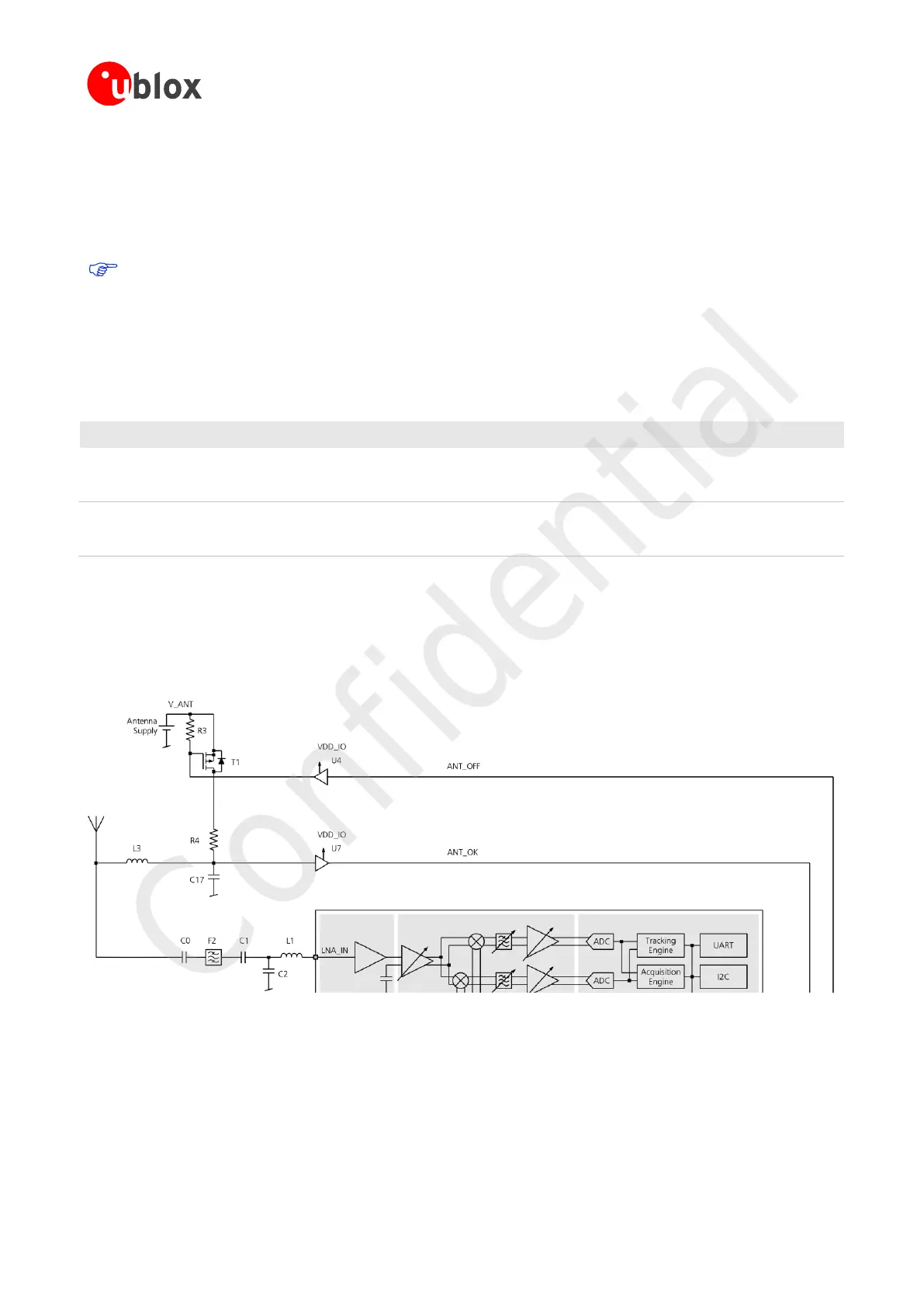
The circuitry as shown in Figure 7 provides antenna supply short circuit detection. It will prevent antenna
operation via transistor T1 if a short circuit has been detected or if it is not required (e.g. in Power Save Mode).
The status of the active antenna can be checked by UBX-MON-HW message. See the u-blox 7 Receiver
Description including Protocol Specification [3].
Figure 7: 2-pin Antenna Supervisor
If the antenna supply voltage V_ANT exceeds VDD_IO, open drain buffers U4 and U7 (e.g. Fairchild
NC7WZ07) are needed to shift the voltage levels. R3 is required as a passive pull-up to control T1 because U4
has an open drain output. R4 serves as a current limiter in the event of a short circuit.
 Loading...

