ZOE-M8 series - Hardware Integration Manual
UBX-16030136 - R07 Production Information Design-in
Page 13 of 32
2.5.2 Improved jamming immunity
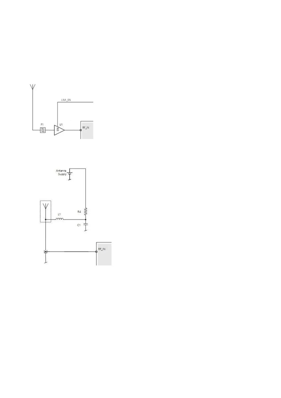
If strong out-band jammers are close to the GNSS antenna (e.g. a GSM antenna), GNSS performance can be
degraded or the maximum input power of the ZOE-M8 GNSS SiPs RF-input can be exceeded. In that case, the
SAW filter (F1) must be put in front of the external LNA (U1).
It should be noted that the insertion loss of the SAW filter (F1) directly affects the system noise figure and hence
the system performance.
Figure 6: Circuit for improved jamming immunity
2.5.3 Active antenna
In case an active antenna is used, the active antenna supply circuit must be added just in front of the SiPs RF-input.
Figure 7: Active antenna supply circuit
2.6 Safe Boot Mode (SAFEBOOT_N)
If the SAFEBOOT_N pin is “low” at start-up, the ZOE-M8 GNSS SiPs start in Safe Boot Mode and does not begin
GNSS operation. In Safe Boot Mode, the SiP runs from an internal LC oscillator and starts regardless of any
configuration provided by the configuration pins. Thus, it can be used to recover from situations where the SQI
flash has become corrupted.
For communication by UART in Safe Boot Mode, a training sequence (0x 55 55 at 9600 baud) can be sent by the
host to the ZOE-M8 GNSS SiPs in order to enable communication. After sending the training sequence, the host
must wait for at least 2 ms before sending messages to the receiver. For further information, see the u-blox 8 / u-
blox M8 Receiver Description Including Protocol Specification [2].
Safe Boot Mode is used in production to program the SQI flash. It is recommended to have the possibility to pull
the SAFEBOOT_N pin “low” when the SiP starts up. This can be provided using an externally connected test point
or via a host CPUs digital I/O port.
 Loading...


