ZOE-M8 series - Hardware Integration Manual
UBX-16030136 - R07 Production Information Design-in
Page 22 of 32
• Weakly shielded lines on PCB (e.g. on top or bottom layer and especially at the border of a PCB)
• Weak GND concept (e.g. small and/or long ground line connections)
EMI protection measures are recommended when RF emitting devices are near the GNSS receiver. To minimize
the effect of EMI, a robust grounding concept is essential. To achieve electromagnetic robustness, follow the
standard EMI suppression techniques.
http://www.murata.com/products/emc/knowhow/index.html
http://www.murata.com/products/emc/knowhow/pdf/4to5e.pdf
Improved EMI protection can be achieved by inserting a resistor or, better yet, a ferrite bead or an inductor (see
Table 16) into any unshielded PCB lines that are connected to the GNSS receiver. Place the resistor as close as
possible to the GNSS receiver pin.
Alternatively, feed-thru capacitors with good GND connection can be used to protect e.g. the VCC supply pin
against EMI. A selection of feed-thru capacitors are listed in Table 16.
Intended use
In order to mitigate any performance degradation of a radio equipment under EMC disturbance, system
integration shall adopt appropriate EMC design practice and not contain cables over three meters on signal
and supply ports.
2.13.6 Applications with cellular modules
GSM terminals transmit power levels up to 2 W (+33 dBm) peak, 3G and LTE up to 250 mW continuous. Consult
the ZOE-M8 Data Sheet [1] for the absolute maximum power input at the GNSS receiver. Make sure that the
absolute maximum input power level of the GNSS receiver is not exceeded.
See the GPS Implementation and Aiding Features in u-blox wireless modules [5].
2.13.6.1 Isolation between GNSS and GSM antenna
In a handheld type design, an isolation of approximately 20 dB can be reached with careful placement of the
antennas. If such isolation can’t be achieved, e.g. in the case of an integrated GSM/GNSS antenna, then an
additional input filter is needed on the GNSS side to block the high energy emitted by the GSM transmitter.
Examples of these kinds of filters would be the SAW Filters from Epcos (B9444 or B7839) or Murata.
2.13.6.2 Increasing interference immunity
Interference signals come from in-band and out-band frequency sources.
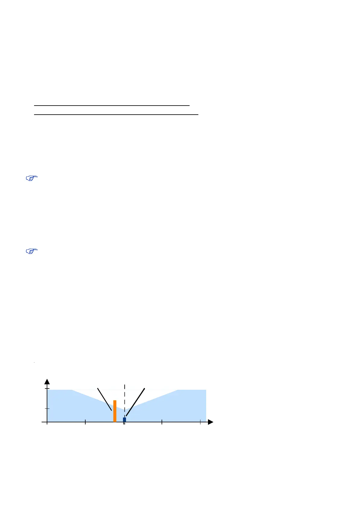
2.13.6.3 In-band interference
With in-band interference, the signal frequency is very close to the GPS frequency of 1575 MHz (see Figure 16).
Such interference signals are typically caused by harmonics from displays, micro-controllers, bus systems, etc.
1525 1550 1625
GPS input filter
characteristics
1575 1600
0
-110
Jammi n
g signal
1525 1550 1625
Frequency [MHz]
Power [dBm]
GPS input filter
characteristics
1575 1600
0
Interference
signal
GPS
signals
GPS Carrier
1575.4 MHz
Figure 16: In-band interference signals
 Loading...


