Ubee Interactive Understanding the Device Panels, Connections and LEDs
Ubee DVW32CB Advanced Wireless Voice Gateway Subscriber User Guide • January 2015 6
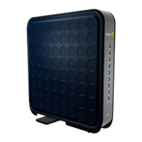
1.5.2 Understanding the Device Connections
The following table describes the connections on the device.
1.5.3 Understanding LED Behavior
The following tables summarize the behavior of the LEDs on both the front and rear
panels of the DVW32CB.
Item Description
TEL 1/2
TEL 2
Connects to standard telephones using an RJ11 cable. Telephone
service must be enabled by your service provider.
ETHERNET 1 - 4 Connects to Ethernet devices such as computers, gaming consoles,
and/or routers/hubs using an RJ45 cable. Each ETHERNET port on
the back panel of the device has an LED to indicate its status when
an Ethernet device is connected.
RESET Restores the settings of the device including wireless and custom
gateway settings. Use a pointed object to push down the reset
button until the power LED turns off. After the power LED turns off,
release the button.
CABLE Connects to the cable outlet (with the cable provided by your
service provider), or a cable splitter connected to the cable outlet.
POWER Connects the power cable to the device. Use only the power cable
provided with the DVW32CB.
WPS Located on top of the cable modem, this button is used for the WiFi
Protected Setup (WPS) method to connect a PIN-protected WiFi
device to the cable modem. Refer to Understanding the Wireless
Menu on page 74 for more information.
FRONT PANEL
LED Color Description
POWER Blue On – Internal power-on completed successfully.
Flashes – Power-on failed. Note that the LED blinks briefly immediately after powering on the
device.
DS/US
(downstream/
upstream)
Blue Flashes – Once every second while scanning DS/US. Once locked on DS/US, flashes twice
every second while registering the DS/US.
On – Locked to DS/US channels and registered OK.
Flashes – When a firmware upgrade is in progress, and POWER LED and ONLINE LEDs are
ON solid.
ONLINE Blue Flashes – Obtaining an IP address and configuration file.
On – Configuration completed successfully, network connected.
Off – Network connect failed.
2.4G Blue On – 2.4G WiFi is enabled.
Off – 2.4G WiFi is disabled.
5G Blue On – 5G WiFi is enabled.
Off – 5G WiFi is disabled.