MAX-M10M-Integration manual
The open drain buffers shown in Figure 10 are not needed if V_ANT is the same voltage level
as V_IO.
3.3.1.2 Two-pin antenna supervisor
The reduced functionality antenna supervisor circuit is connected to two signals: antenna control
(ANT_OFF_N) and antenna status detection (ANT_SHORT_N). The ANT_OFF_N signal is already
enabled and assigned to the LNA_EN pin in MAX-M10M and the ANT_SHORT_N signal can be
assigned to any unused PIO, which may require disabling the previous function of the PIO. To
enable the reduced antenna supervisor, the ANT_SHORT_N signal must be enabled in the receiver
configuration. The polarity of the ANT_SHORT_N signal must also be defined in the receiver
configuration based on the design use case.
The antenna can be supplied by VCC_RF or an external supply. Note that the supply voltage must be
clean, as any noise could directly couple into the RF part of the GNSS receiver affecting the overall
GNSS performance.
Refer to Reference designs for antenna supervisor examples and the required configuration.
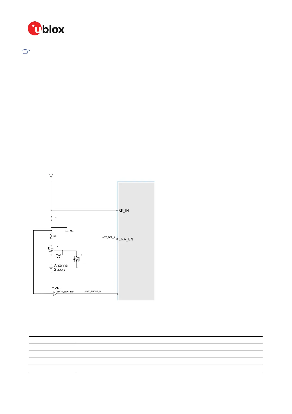
Figure 11 presents the required two-pin antenna supervisor circuit and subsequent sections
describe how to enable and monitor each feature.
Figure 11: MAX-M10M two-pin antenna supervisor
Table 17 presents a list of the external components required for implementing the two-pin antenna
supervisor design in Figure 11. Refer to External components for the recommended parts and
specification.
Part Description
C14 Filtering capacitor
T1, T2 p-channel, n-channel MOSFET acting as a switch to control the antenna supply
U7 Open drain buffers to shift voltage levels
R7 Passive pull-up to control T1
UBX-22038241 - R02
3 Receiver functionality Page 30 of 92
C1-Public