MAX-M10M-Integration manual
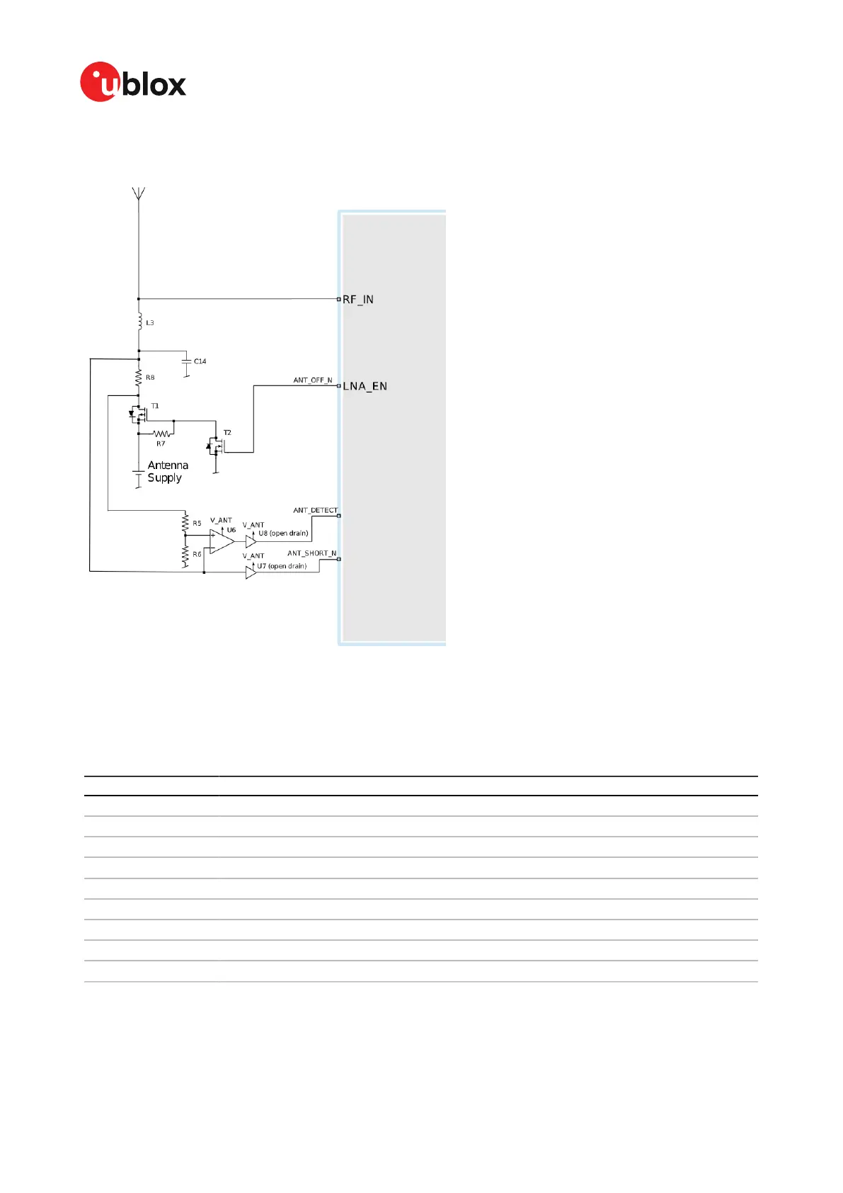
Figure 10 presents the required three-pin antenna supervisor circuit and subsequent sections
describe how to enable and monitor each feature.
Figure 10: MAX-M10M three-pin antenna supervisor
Table 16 presents a list of the external components required for implementing the three-pin antenna
supervisor design in Figure 10. Refer to External components for the recommended parts and
specification.
Part Description
C14 Filtering capacitor
L3 DC infeed inductor
T1, T2 p-channel, n-channel MOSFET acting as a switch to control the antenna supply
U6 Comparator (op-amp)
U7, U8 Open drain buffers to shift voltage levels
R7 Passive pull-up to control T1
R8 Current limiter in the event of a short circuit
R5 Defines the threshold of the comparator
R6 Defines the threshold of the comparator
Table 16: Components in antenna supervisor
The threshold voltage (V_REF) of the comparator is defined by R5 and R6. It can be calculated as:
V_REF = R6/(R6+R5)*V_ANT.
UBX-22038241 - R02
3 Receiver functionality Page 29 of 92
C1-Public

 Loading...


