MAX-M10M-Integration manual
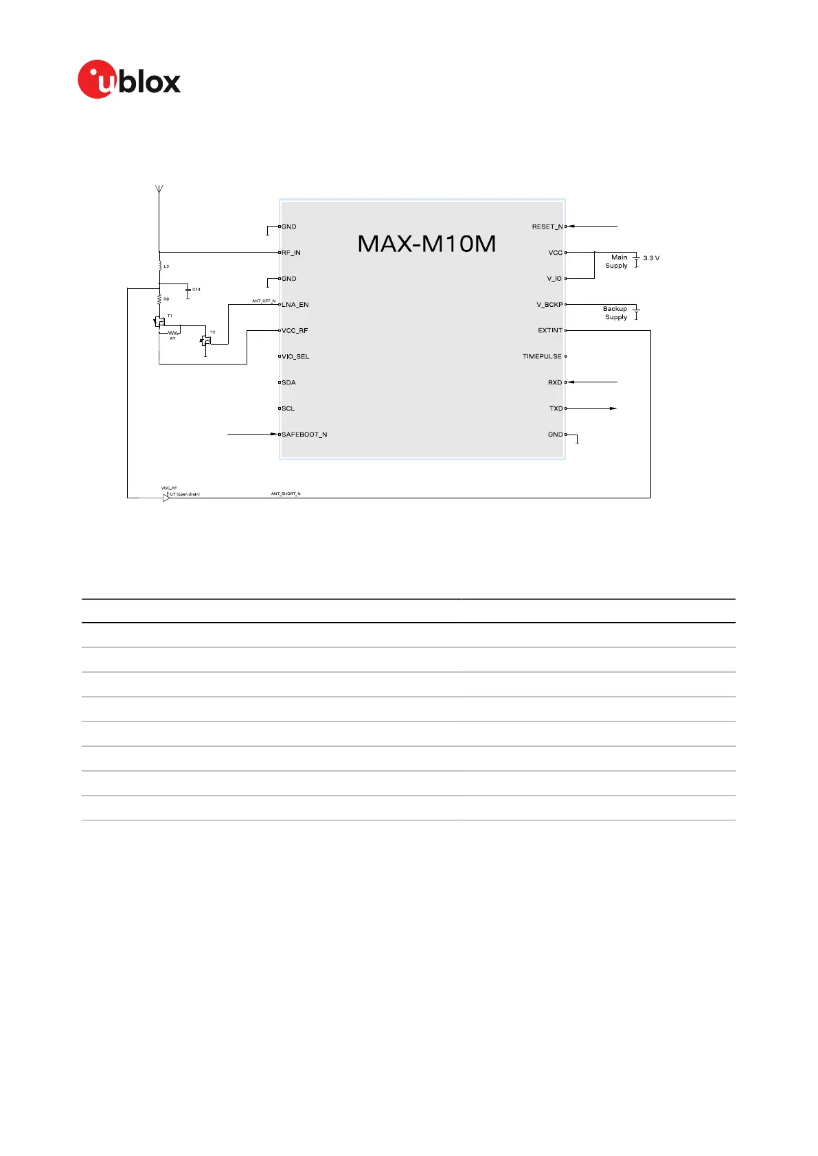
Figure 38: 2-pin antenna supervisor design
The 2-pin antenna supervisor configuration required for the Figure 38 reference design is listed in
Table 35.
Configuration key Value
CFG-HW-ANT_CFG_VOLTCTRL 1 (true), default (no configuration required)
CFG-HW-ANT_SUP_SWITCH_PIN 7, default (no configuration required)
CFG-HW-ANT_CFG_SHORTDET 1 (true)
CFG-HW-ANT_CFG_SHORTDET_POL 0 (false)
CFG-HW-ANT_SUP_SHORT_PIN 5
CFG-HW-ANT_CFG_PWRDOWN 1 (true)
CFG-HW-ANT_CFG_PWRDOWN_POL 0 (false), default (no configuration required)
CFG-HW-ANT_CFG_RECOVER 1 (true)
Table 35: Configuration for the 2-pin antenna supervisor design
UBX-22038241 - R02
Appendix Page 87 of 92
C1-Public