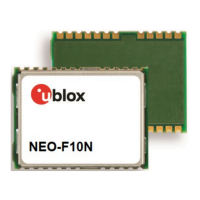
NEO-F10N-Integration manual
C External components
This section lists the recommended values for the external components in the reference designs.
C.1 Standard capacitors
Table 15 presents the recommended capacitor values for NEO-F10N.
Name Use Type / Value
C14 RF Bias-T capacitor 10 nF, 10%, 16 V, X7R
Table 15: Standard capacitors
C.2 Standard resistors
Table 16 presents the recommended resistor values for NEO-F10N.
Name Use Type / Value
R7 Pull-up resistor at antenna switch transistor 100 kΩ, 5%, 0.1 W
R8 Antenna supply current limiter/shunt resistor 10 Ω, 5%, 0.25 W
R17 Current limiter to supply antenna through VCC_RF 10 Ω, 5%, 0.1 W
R18 Current limiter to supply antenna through VCC_RF 220 Ω, 5%, 0.1 W
R20 Current limiter to supply antenna through VCC_RF 2.2 kΩ, 5%, 0.1 W
Table 16: Standard resistors
C.3 Inductors
Table 17 presents the recommended inductor values for NEO-F10N.
Name Use Type / Value Recommended component
L4 RF Bias-T inductor 47 nH, 5%
Murata LQG15HS47NJ02
Johanson Technology L-07W series
Any other inductor with impedance > 500 Ω at GNSS L1 and L5
frequencies and current rating above 300 mA.
Table 17: Recommended inductors
C.4 Switch transistors for antenna supply
Table 18 presents the recommended switch transistors for NEO-F10N.
Name Manufacturer Order no. Comments
T1, T2 Vishay Si1016X-T1-GE3 p-channel, n-channel MOSFET
T6, T7 - BC857C BJT PNP transistor
Table 18: Recommended parts list for the antenna supply switch transistors
UBXDOC-963802114-12193 - R02
Appendix Page 39 of 42
C1-Public

 Loading...