NEO-F10N-Integration manual
1.3 Pin definition
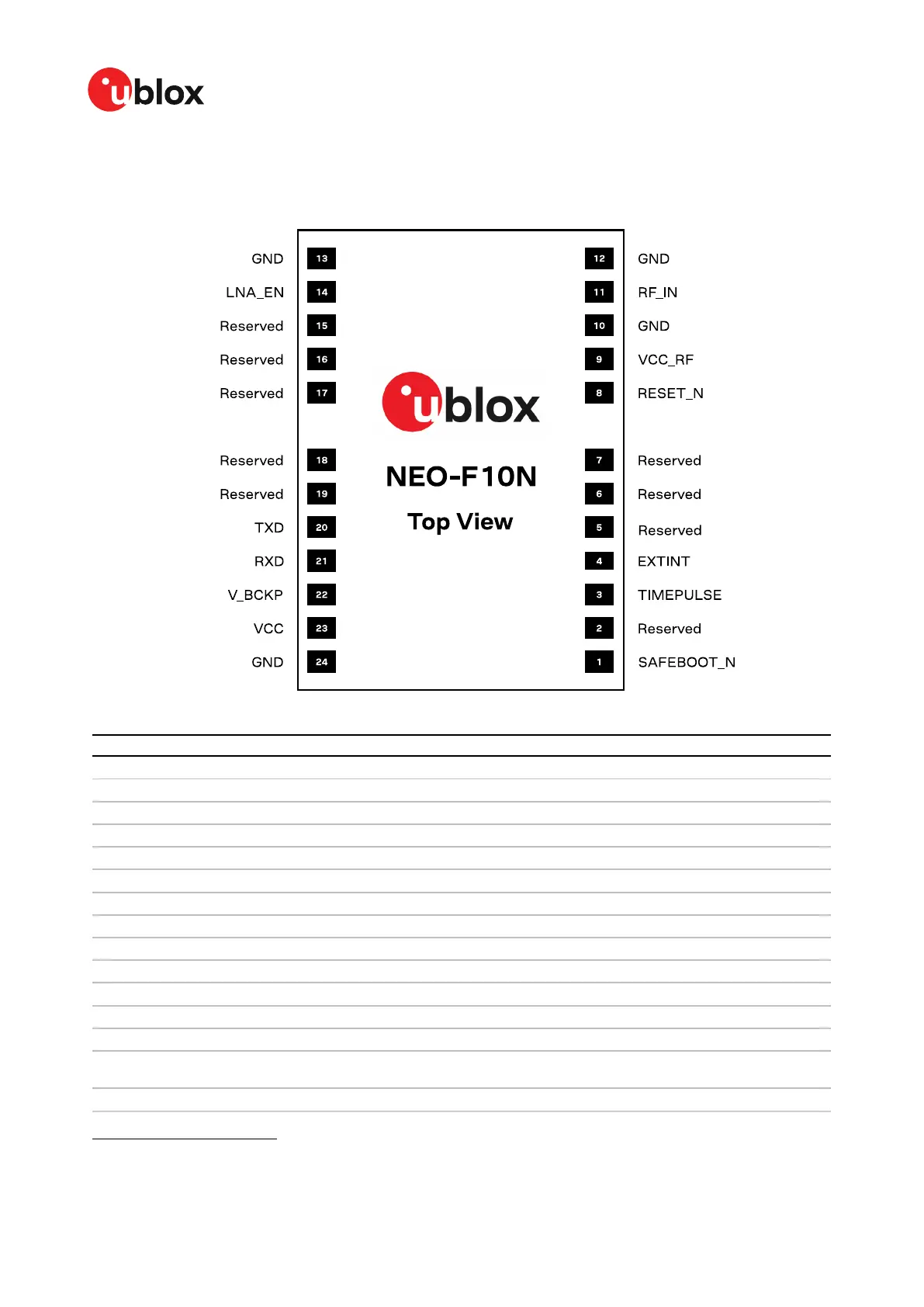
1.3.1 Pin assignment
Figure 2: NEO-F10N pin assignment
Pin no. Name I/O Description
1 SAFEBOOT_N I Safeboot mode (leave open)
2 Reserved - Not connected
3 TIMEPULSE O Time pulse signal (shared with SAFEBOOT_N pin)
4 EXTINT I External interrupt
5 Reserved - Not connected
6 Reserved - Not connected
7 Reserved - Not connected
8 RESET_N I RESET (active low)
9 VCC_RF O Output voltage RF section
10 GND - Ground
11 RF_IN I GNSS signal input
12 GND - Ground
13 GND - Ground
14 LNA_EN O On/Off internal LNAs and an optional external LNA or an active
antenna
15 Reserved - Not connected
1
The receiver enters safeboot mode if this pin is low at start up. The SAFEBOOT_N pin is internally connected to
TIMEPULSE pin through a 1 kΩ series resistor.
UBXDOC-963802114-12193 - R02
1 System description Page 6 of 42
C1-Public

 Loading...


