SARA-R5 series - System integration manual
UBX-19041356 - R04 System description Page 22 of 118
C1-Public
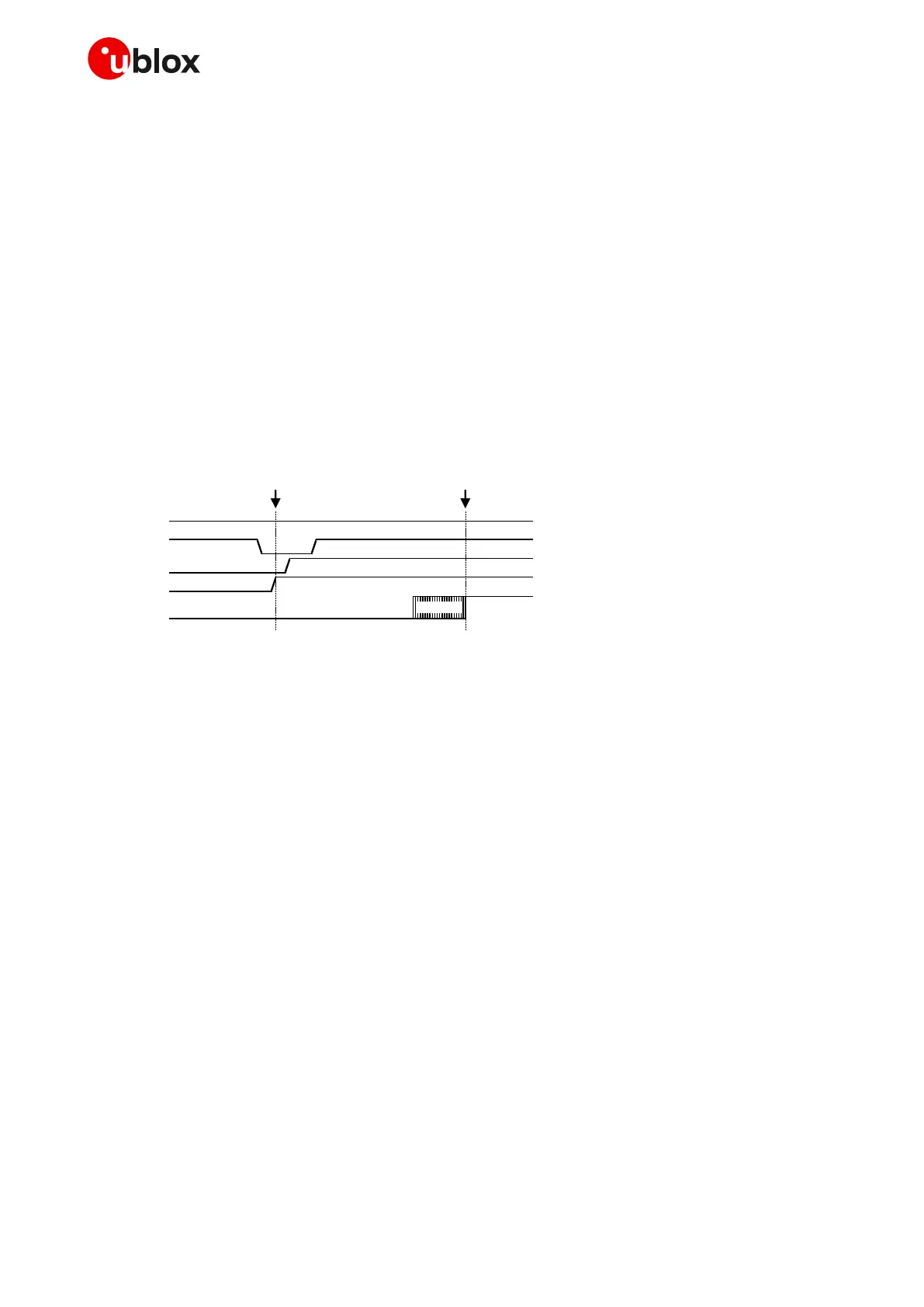
1.6.1.3 Switch-on / wake-up sequence from power-off / deep-sleep mode
Figure 14 shows the SARA-R5 series modules switch-on or wake-up sequence from the power-off or
deep-sleep mode:
• The external power supply is still applied to the VCC module pins, with the module being previously
switched off (by means of the +CPWROFF AT command or by proper PWR_ON pin toggling), or
with the module being previously entered deep-sleep mode.
• The PWR_ON pin is held low for a valid time period, representing the start-up event.
• All the generic digital pins are tri-stated until the switch-on of their supply source (V_INT).
• The baseband core and all digital pins are held in reset state; then, any digital pin is set in the
correct sequence from the reset state to the default operational configured state. The duration of
this phase differs within generic digital interfaces and USB interface due to host / device
enumeration timings.
• If enabled, a greeting message is sent on the RXD pin (for more details, see SARA-R5 series AT
commands manual [2]).
• The module is fully ready to operate after all interfaces are configured.
Figure 14: SARA-R5 series switch-on / wake-up sequence description from power-off / deep-sleep mode
1.6.1.4 General considerations for the switch-on procedure
If the greeting text is not used by the external application to detect that the module is ready to reply
to AT commands, then the only way of checking it is polling: the external application can start sending
“AT” after that the CTS line is set to the ON state (in case UART is used as AT interface with HW flow
control enabled as default), but any AT command sent before the time when the module is ready to
reply may be not buffered and may be lost.
☞ It is highly recommended to monitor:
o the V_INT pin, to sense the start of the SARA-R5 series module switch-on sequence
o the GPIO pin configured to provide the module status indication or module operating mode
indication (see SARA-R5 series AT commands manual [2], +UGPIOC), to sense when the
module is ready to operate
☞ No voltage driven by an external application should be applied to any generic digital interface of
the module before the initialization of the interfaces has been finished, detectable by “greeting
text” (if enabled) or by CTS line going low (if HW flow control is enabled as default).
☞ The duration of the SARA-R5 series modules’ switch-on routine can vary depending on the
application / network settings and the concurrent module activities: Figure 12, Figure 13 and Figure
14 illustrate indicative typical timings only.
☞ It is highly recommended to avoid an abrupt removal of the VCC supply once the boot of SARA-R5
series modules has been triggered.

 Loading...


