SARA-R5 series - System integration manual
UBX-19041356 - R04 System description Page 21 of 118
C1-Public
1.6.1.2 Switch-on sequence from not-powered mode
Figure 12 shows the SARA-R500S / SARA-R510M8S switch-on sequence from not-powered mode:
• The external power supply is applied to the VCC module pins, representing the start-up event.
• All the generic digital pins are tri-stated until the switch-on of their supply source (V_INT).
• The baseband core and all digital pins are held in reset state; then, any digital pin is set in the
correct sequence from the reset state to the default operational configured state. The duration of
this phase differs within generic digital interfaces and USB interface due to host / device
enumeration timings.
• If enabled, a greeting message is sent on the RXD pin (for more details, see SARA-R5 series AT
commands manual [2]).
• The module is fully ready to operate after all interfaces are configured.
Module interfaces
are configured
Figure 12: SARA-R500S / SARA-R510M8S switch-on sequence description from not-powered mode
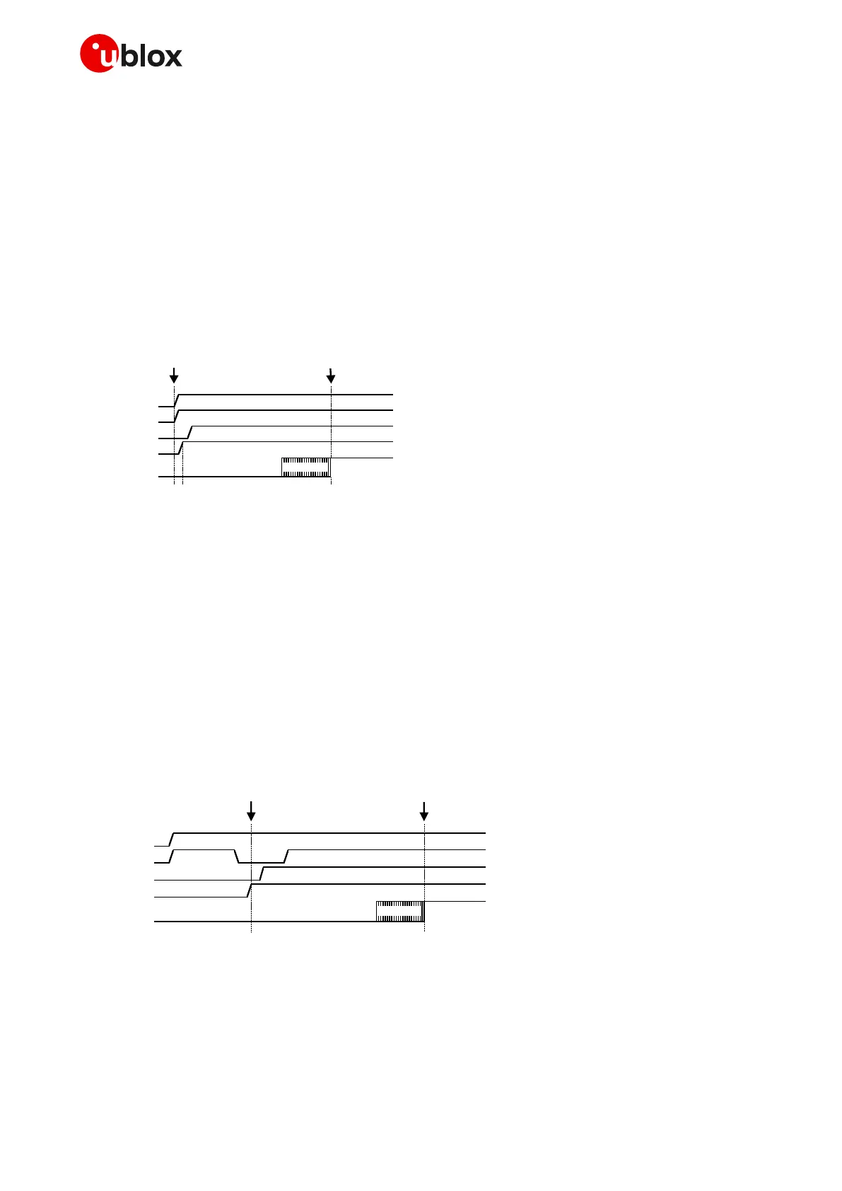
Figure 13 shows the SARA-R510S modules switch-on sequence from the not-powered mode:
• The external power supply is applied to the VCC module pins.
• The PWR_ON pin is held low for a valid time period, representing the start-up event.
• All the generic digital pins are tri-stated until the switch-on of their supply source (V_INT).
• The baseband core and all digital pins are held in reset state; then, any digital pin is set in the
correct sequence from the reset state to the default operational configured state. The duration of
this phase differs within generic digital interfaces and USB interface due to host / device
enumeration timings.
• If enabled, a greeting message is sent on the RXD pin (for more details, see SARA-R5 series AT
commands manual [2]).
• The module is fully ready to operate after all interfaces are configured.
Module interfaces
are configured
Figure 13: SARA-R510S switch-on sequence description from not-powered mode

 Loading...


