SARA-R5 series - System integration manual
UBX-19041356 - R04 Design-in Page 46 of 118
C1-Public
The battery charger IC, as linear charger, is more suitable for applications where the charging source
has a relatively low nominal voltage (~5 V), so that a switching charger is suggested for applications
where the charging source has a relatively high nominal voltage (e.g. ~12 V, see section 2.2.1.7 for the
specific design-in).
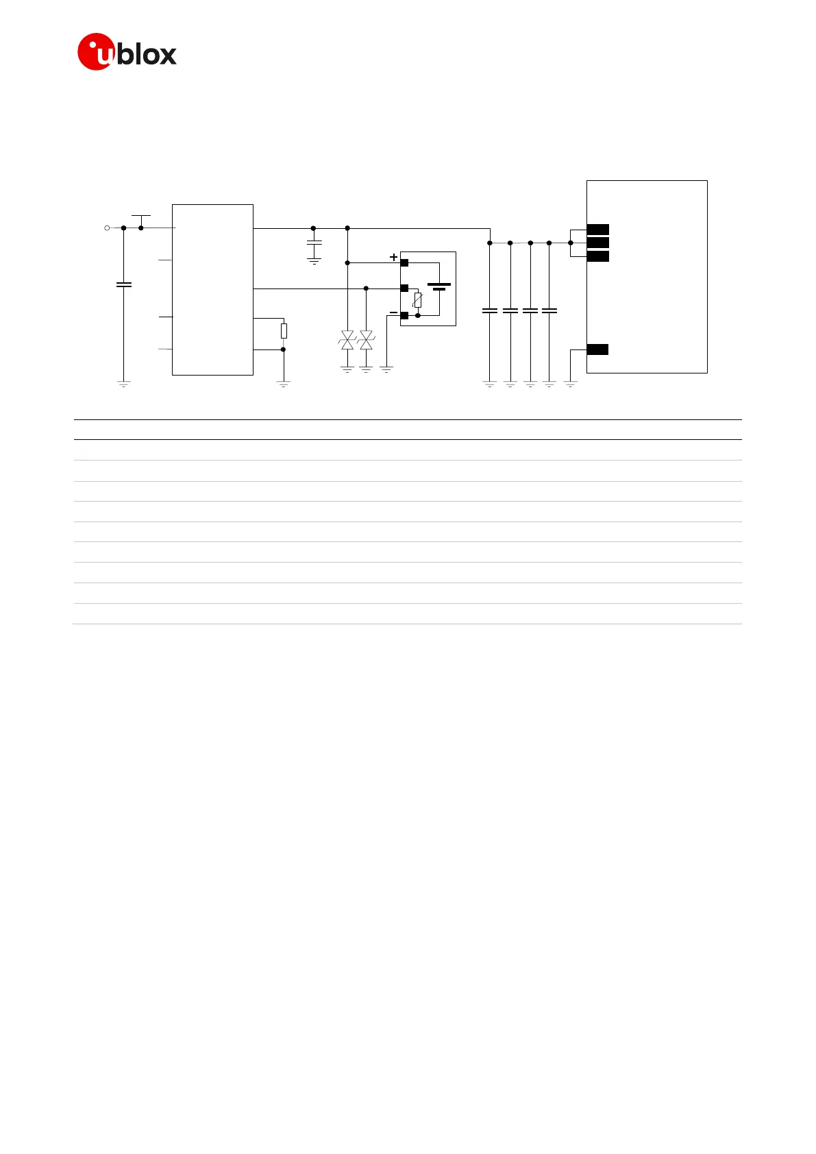
C5C3 C6
GND
SARA-R5 series
52
VCC
53
VCC
51
VCC
USB
supply
θ
U1
PG
STAT2
STA1
VDD
C1
5V0
THERM
Vss
Vbat
Li-Ion/Li-Pol
battery pack
D1
B1
C2
Li-Ion/Li-Pol
battery charger IC
D2
PROG
R1
C4
Figure 24: Li-Ion (or Li-Pol) battery charging application circuit
Part number - Manufacturer
Li-Ion (or Li-Pol) battery pack with 470 NTC
1 F capacitor ceramic X7R 16 V
15 pF capacitor ceramic C0G 0402 5% 50 V
GRM1555C1H150JB01 - Murata
68 pF capacitor ceramic C0G 0402 5% 50 V
GRM1555C1H680JA16 - Murata
10 nF capacitor ceramic X7R 0402 10% 16 V
GRT155R71C103KE01 - Murata
100 nF capacitor ceramic X7R 0402 10% 16 V
GCM155R71C104KA55 - Murata
Low capacitance ESD protection
Single cell Li-Ion (or Li-Pol) battery charger IC
Table 12: Suggested components for the Li-Ion (or Li-Pol) battery charging application circuit
☞ See the section 2.2.1.9, and in particular Figure 28 / Table 15, for the parts recommended to be
provided if the application device integrates an internal antenna.
2.2.1.7 Guidelines for external charging and power path management circuit
Application devices where both a permanent primary supply / charging source (e.g. ~12 V) and a
rechargeable back-up battery (e.g. 3.7 V Li-Pol) are available at the same time as a possible supply
source, should implement a suitable charger / regulator with integrated power path management
function to supply the module and the whole device while simultaneously and independently charging
the battery.
Figure 25 reports a simplified block diagram circuit showing the working principle of a charger /
regulator with integrated power path management function. This component allows the system to be
powered by a permanent primary supply source (e.g. ~12 V) using the integrated regulator, which
simultaneously and independently recharges the battery (e.g. 3.7 V Li-Pol) that represents the
back-up supply source of the system. The power path management feature permits the battery to
supplement the system current requirements when the primary supply source is not available or
cannot deliver the peak system currents.

 Loading...


