SARA-R5 series - System integration manual
UBX-19041356 - R04 Design-in Page 49 of 118
C1-Public
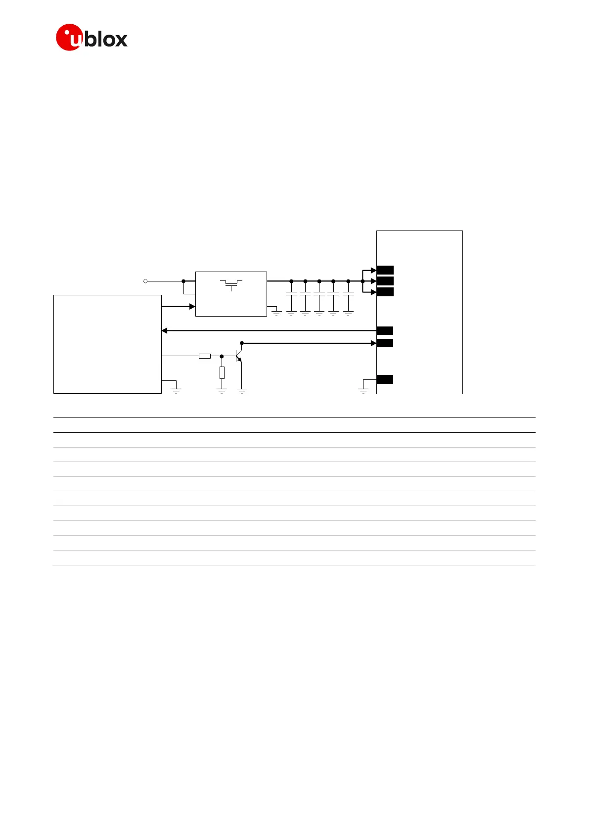
2.2.1.8 Guidelines for removing VCC supply
Removing the VCC power can be useful to minimize the current consumption when the SARA-R500S
and SARA-R510M8S modules are switched off. The application processor can disconnect the VCC
supply source from the module and zero out the module’s current.
The VCC supply source can be removed using an appropriate low-leakage load switch or p-channel
MOSFET controlled by the application processor as shown in Figure 27, using an external switch with:
• Very low leakage current (for example, less than 60 A), to minimize the current consumption
• Very low R
DS(ON)
series resistance (for example, less than 50 m), to minimize voltage drops
• Adequate maximum drain current (see the SARA-R5 series data sheet [1] for module current
consumption figures)
C3
GND
C2C1 C4
SARA-R5 series
52
VCC
53
VCC
51
VCC
VCC supply source
GND
C5
U1
VOUTVIN
VBIAS
ON
CT
GND
4
V_INT
15
PWR_ON
R1
R2
T1
GPIO
Application
Processor
GPIO
GPIO
Figure 27: Example of application circuit for VCC supply removal
Part number - Manufacturer
10 µF capacitor ceramic X5R 0603 20% 6.3 V
GRM188R60J106ME47 - Murata
10 nF capacitor ceramic X7R 0402 10% 16 V
GRT155R71C103KE01 - Murata
100 nF capacitor ceramic X7R 0402 10% 16 V
GCM155R71C104KA55 - Murata
68 pF capacitor ceramic C0G 0402 5% 50 V
GRM1555C1H680JA16 - Murata
15 pF capacitor ceramic C0G 0402 5% 25 V
GJM1555C1H150JB01 - Murata
47 k resistor 0402 5% 0.1 W
10 k resistor 0402 5% 0.1 W
Ultra-low resistance load switch
TPS22967 - Texas Instruments
Table 14: Components for VCC supply removal application circuit
☞ It is highly recommended to avoid an abrupt removal of the VCC supply during SARA-R5 series
normal operations: the VCC supply can be removed only after V_INT goes low, indicating that the
module has entered deep-sleep power saving mode or power-off mode.
☞ In case of applications where an abrupt power removal cannot be avoided, it is recommended to
set the RESET_N input line at the low logic level as soon as the power failure in the supply source
is detected, so that the under-voltage shutdown may be executed more safely since ~450 ms after
the falling edge at the RESET_N input line.
☞ See the section 2.2.1.9, and in particular Figure 28 / Table 15, for the parts recommended to be
provided if the application device integrates an internal antenna.

 Loading...


