SARA-R5 series - System integration manual
UBX-19041356 - R04 Design-in Page 56 of 118
C1-Public
2.4.1.2 Guidelines for RF transmission lines design
☞ The GNSS antenna RF interface is not supported by SARA-R500S and SARA-R510S modules.
Any RF transmission line, such as the ones from the ANT and ANT_GNSS pads up to the related
antenna connector or up to the related internal antenna pad, must be designed so that the
characteristic impedance is as close as possible to 50 .
RF transmission lines can be designed as a micro strip (consists of a conducting strip separated from
a ground plane by a dielectric material) or a strip line (consists of a flat strip of metal which is
sandwiched between two parallel ground planes within a dielectric material). The micro strip,
implemented as a coplanar waveguide, is the most common configuration for printed circuit board.
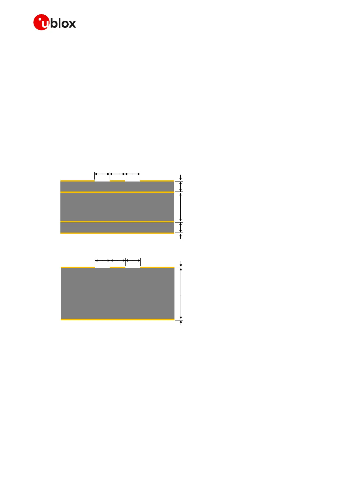
Figure 33 and Figure 34 provide two examples of suitable 50 coplanar waveguide designs. The first
example of RF transmission line can be implemented in case of 4-layer PCB stack-up herein described,
and the second example of RF transmission line can be implemented in case of 2-layer PCB stack-up
herein described.
35 µm
35 µm
35 µm
35 µm
270 µm
270 µm
760 µm
L1 copper
L3 copper
L2 copper
L4 copper
FR-4 dielectric
FR-4 dielectric
FR-4 dielectric
380 µm 500 µm500 µm
Figure 33: Example of 50 coplanar waveguide transmission line design for the described 4-layer board layup
35 µm
35 µm
1510 µm
L2 copper
L1 copper
FR-4 dielectric
1200 µm 400 µm400 µm
Figure 34: Example of 50 coplanar waveguide transmission line design for the described 2-layer board layup
If the two examples do not match the application PCB stack-up, then the 50 characteristic
impedance calculation can be made using the HFSS commercial finite element method solver for
electromagnetic structures from Ansys Corporation, or using freeware tools like Avago / Broadcom
AppCAD (https://www.broadcom.com/appcad) taking care of the approximation formulas used by the
tools for the impedance computation.
To achieve a 50 characteristic impedance, the transmission line width must be chosen due to:
• the thickness of the transmission line itself (e.g. 35 m in the example of Figure 33 and Figure 34)
• the thickness of the dielectric material between the top layer (where the line is routed) and the
inner closer layer implementing the ground plane (e.g. 270 m in Figure 33, 1510 m in Figure 34)
• the dielectric constant of the dielectric material (e.g. dielectric constant of the FR-4 dielectric
material in Figure 33 and Figure 34)
• the gap from the transmission line to the adjacent ground plane on the same layer of the
transmission line (e.g. 500 m in Figure 33, 400 m in Figure 34)

 Loading...


