SARA-R5 series - System integration manual
UBX-19041356 - R04 Design-in Page 71 of 118
C1-Public
• ensuring at least 15 – 20 dB isolation between antennas in the GNSS band by implementing the
most suitable placement for the antennas, considering in particular the related radiation diagrams
of the antennas: better isolation results from antenna patterns with radiation lobes in different
directions considering the GNSS frequency band.
• adding a GNSS pass-band SAW filter along the GNSS RF line, providing very large attenuation in
the cellular frequency bands (see Table 22 for possible suitable examples). It has to be noted that,
as shown in Figure 3, a SAW filter and an LNA are already integrated in the GNSS RF path of the
SARA-R510M8S: the addition of an external filter along the GNSS RF line has to be considered only
if the conditions above cannot be met.
In case all the aforementioned countermeasures cannot be implemented, adding a GNSS stop-band
SAW filter along the cellular RF line may be considered. The filter shall provide very low attenuation in
the cellular frequency bands (see Table 29 for possible suitable examples). It has to be noted that the
addition of an external filter along the cellular RF line has to be carefully evaluated, considering that
the additional insertion loss of such filter may affect the cellular TRP and/or TIS RF figures.
Table 29 lists examples of GNSS band-stop SAW filters that may be considered for the cellular RF
input/output in case enough isolation between the cellular and the GNSS RF systems cannot be
provided by proper selection and placement of the antennas beside other proper RF design solutions.
Table 29: Examples of GNSS band-stop SAW filters
As far as Tx power is concerned, SARA-R5 series modules maximum output power during LTE
transmission is 23 dBm. High-power transmission occurs very infrequently: typical output power
values are in the range of -3 to 0 dBm (see Figure 1 in the GSMA official document TS.09 [11]).
Therefore, depending on the application, careful PCB layout, antenna selection and placement should
be sufficient to ensure accurate GNSS reception.
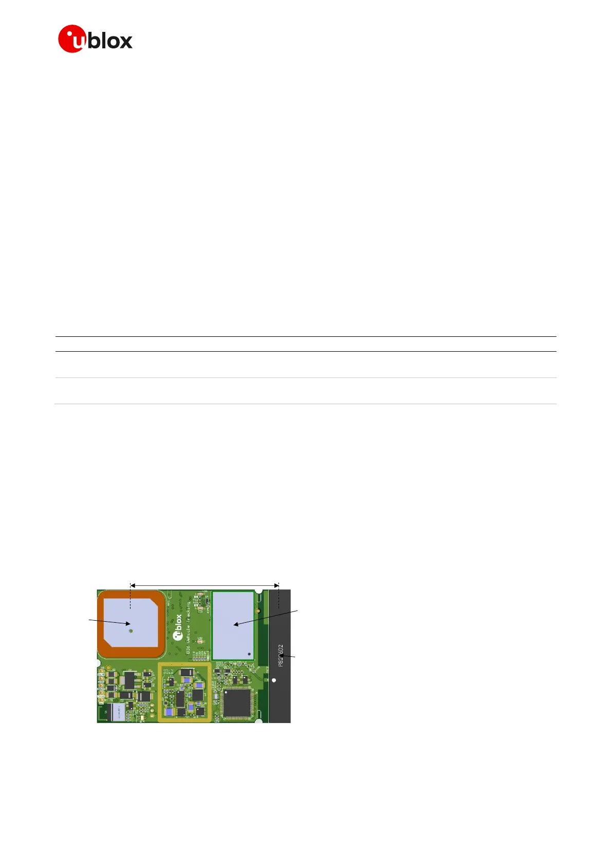
For an example of vehicle tracking application in a small form factor featuring cellular and short-range
connectivity alongside a multi-constellation GNSS receiver, with successful RF coexistence between
the systems, refer to the u-blox B36 vehicle tracking blueprint [17]. The distance between the cellular
and GNSS antennas for the u-blox B36 blueprint is annotated in Figure 47.
Figure 47: PCB top rendering for the u-blox B36 blueprint with annotated distance between cellular and GNSS antennas
☞ For additional information and guidelines regarding the GNSS design, see the SARA-R5 series
positioning implementation application note [18].

 Loading...


