SARA-R5 series - System integration manual
UBX-19041356 - R04 Design-in Page 86 of 118
C1-Public
Providing 2 UARTs with the TXD and RXD lines only
☞ Compatible with USIO variants 2/3/4; not compatible with USIO variants 0/1 (see section 1.9.1.1).
☞ Providing the TXD and RXD lines only is not recommended if the multiplexer functionality is used
in the application: providing also at least the HW flow control (RTS and CTS lines) is recommended,
and it is in particular necessary if the low power mode is enabled by +UPSV AT command.
If the functionality of the RTS, CTS, DSR and RI lines is not required in the application, or the lines are
not available, then:
• Connect the module RTS and DSR input lines to GND or respectively to the CTS and RI output of
the module, since the module requires RTS and DSR active (low electrical level) if HW flow control
is enabled (as it is by default)
If RS-232 compatible signal levels are needed, the Maxim MAX13234E voltage level translator can be
used. This chip translates voltage levels from 1.8 V (module side) to the RS-232 standard.
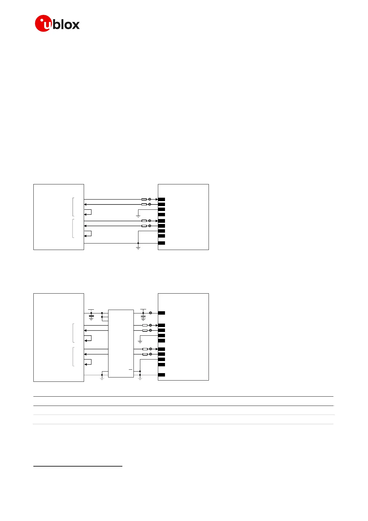
If a 1.8 V application processor (DTE) is used, the circuit should be implemented as in Figure 64.
Figure 64: 2 UART interfaces application circuit with 3-wire links in DTE/DCE serial communications (1.8 V DTE)
If a 3.0 V application processor (DTE) is used, then it is recommended to connect the 1.8 V UART
interfaces of the module (DCE) by means of an appropriate unidirectional voltage translator using the
module V_INT output as 1.8 V supply for the voltage translator on the module side, as in Figure 63.
Table 41: Components for 2 UARTs application circuit with 3-wire links in DTE/DCE serial communications (3.0 V DTE)
☞ Provide accessible test points directly connected to TXD and RXD pins for FW update purpose and
to DCD and DTR pins for diagnostic purpose.

 Loading...


