Doc. 85588U - Rev. 22/10/2020
USER MANUALUSER MANUAL
ENEN
Drw. 32367/h13/54
7.2 Electrical connections
A=
Thecableminimumcrossseconofeachmotorlinecanbecalculatedaccordingtothefollowingformula:
A = crossseconofthelineinmm²
L = line length in m (from control unit to last
lineactuator)
Ι = totalcurrentabsorbed (A)bythe motorsin-
stalled on the line
ΔU=maximumpermittedvoltagedropinthe
line = 2V
Thecontrolunitissuppliedwiththe(RED)posivecabletothebaerydisconnectedandisolatedbymeansoftape,toavoidthe
baerydischargingcompletelyandbeingdamagedbeforeinstallaon.
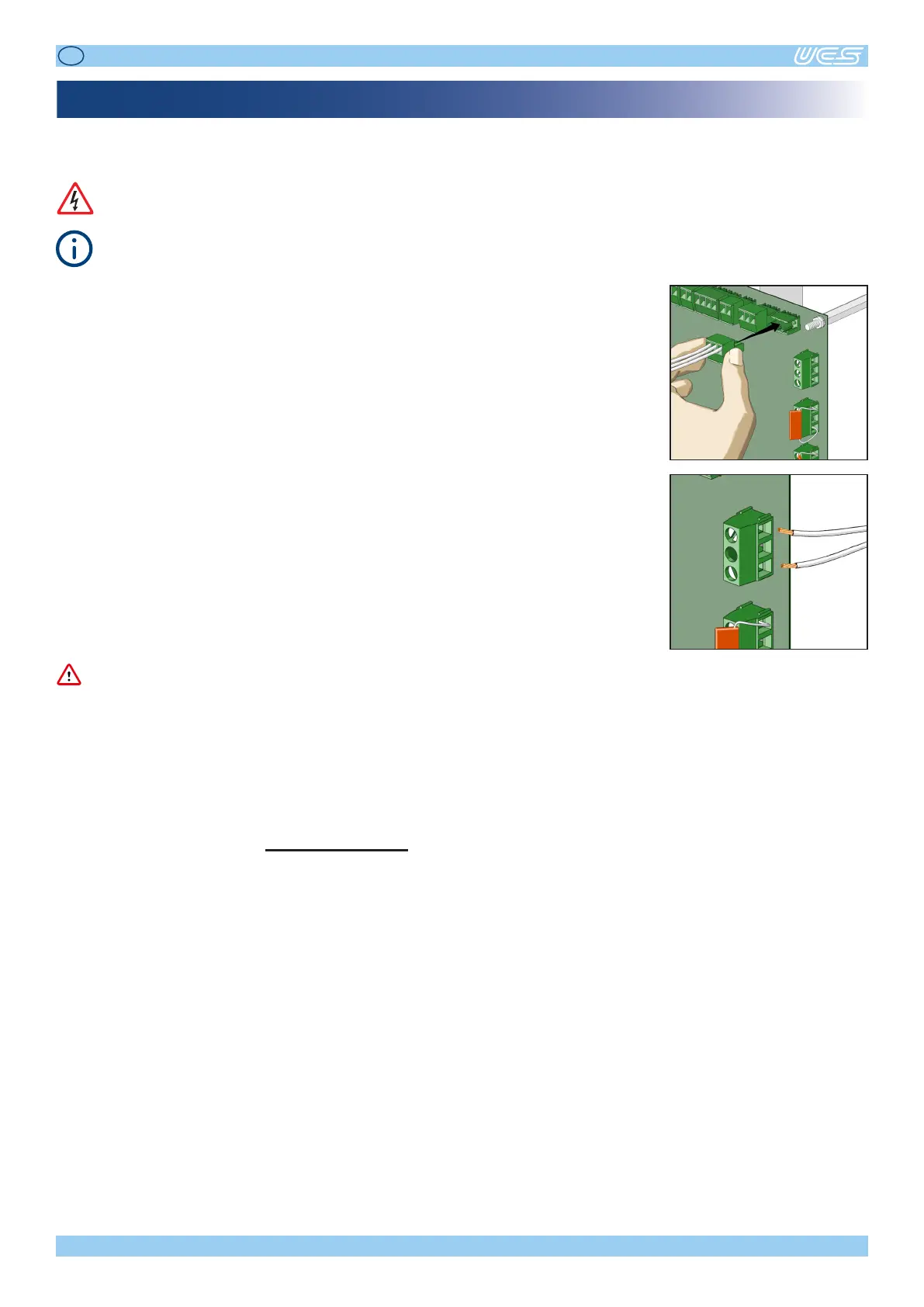
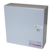
Thecontrolunitisedwithquickcouplingterminals,whichallowquick,opmumconnecon
oftheplant’swires.Theterminalsaresuitableforwireswitha0,5to1,5sq.mmsecon(20to
16AWG).
Seethe“ELECTRICALCONNECTIONS”wiringdiagramsinthismanual.
Thecontrolunitcomeswithsomeresistors/capacitorsedontheconnectors,toallowyoutoswitchitonwithoutanydevice
connected,andwithoutanalarmbeingacvatedonthecontrolunititself.
Whenconnecngtheaccessories(smokesensors,pushbuonpanel,actuators),theseresistors/capacitorsmustbemovedas
showninthe“ELECTRICALCONNECTIONS”diagram:
• the10kOhmresistorsontheSMOKEandEMERGENCYBUTTONterminalsmustbemovedasshownindiagram8onpage52.
• the10kOhmresistorsontheEXTALandEMCLterminalsmustbemovedasshownindiagrams6and7onpage51;
• the4,7uFcapacitorsontheMOTOR1andMOTOR2outputsmustbemovedtotheendofthelines,asshowninthediagram
3onpage50,inordertohavecontroloveranyinterrupons/short-circuitsonthecables.
C
WARNINGWARNING
Themotoroutputsterminalscantakewireswitha1,5to4sq.mmsecon(16to11AWG).
2
x
L
x
Ι
50
x
ΔU