Doc. 85588U - Rev. 22/10/2020
USER MANUALUSER MANUAL
ENEN
Drw. 32367/h14/54
7.3 Calibration
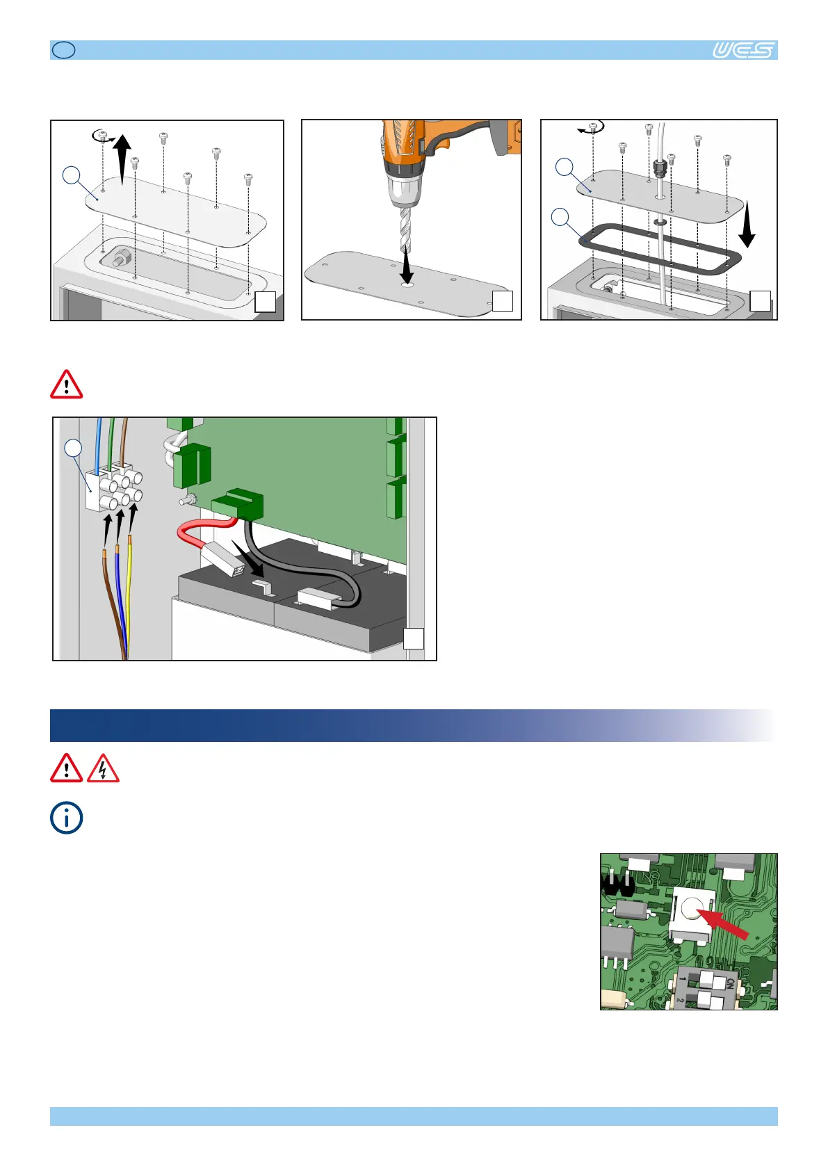
Alltheelectricalconnecons,includingthemainpowersupply,mustreachthecontrolunitthroughthededicatedcover.
Forthatpurpose,proceedasfollows:
7
Removethexingholesfromcover“E”. Drillholesonthecoveraccordingtothe
amount of cables to be connected.
Reposioncover“E”ontheboxequipped
withgasket“F”.
E
8 9
E
F
Connect the power supply cable to terminal “G”.
Connecttheredcabletothebaery.
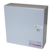
Oncetheinstallaonhasbeencompletedandallconnecons(includingthoserelatedtothe
baeriesandmainspowersupply)havebeenformed,theyellowLEDwillstaylitonthecon-
trolunit(redandgreedLEDso),toindicatethatcalibraonofthetestcircuitryonthemotor
outputsisrequired.Checkthatthecontrolunitandthemotorsareworkingcorrectly,andthen
pushtheCALbuonontheboard.Ifnoerrors,faults,oremergenciesaredetected,thecontrol
unitwillgointoSTANDBYmode,whichisindicatedbyonlythegreenLEDswitchingonand
stayingon.
10
G