6
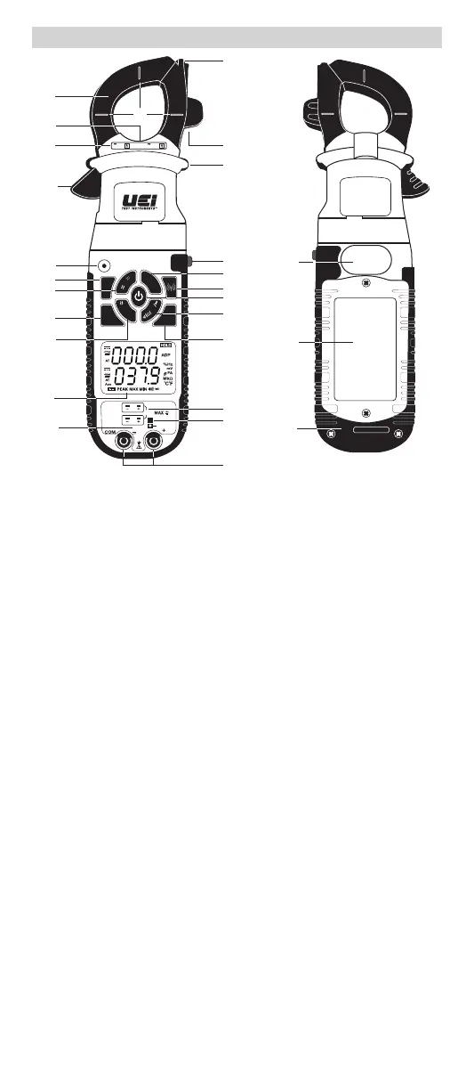
A. Clamp: Measure inductive AC/DC current. Opens to 1.25” (31.7mm).
B. Conductor Alignment Marks: Use to aid the visual alignment of a
conductor when measuring inductive amperage. Greatest accuracy
is achieved when the conductor inside the clamp is centered at the
intersection of these marks.
C. Wire Separation Tab/ NCV sensor: Use to isolate an individual wire from
a bundle for testing. NCV sensor detects live voltage.
D. Test Lead Holder
E. Worklight: Lights clamp area in dark work environments.
F. Category Max Indicator: Maximum CAT Rating for clamp jaw.
G. Hand Guide: Used as a point of reference for the operator’s safety.
H. Clamp Lever: Opens and closes current clamp jaw.
NOTE: The clamp uses a high-tension spring to close the jaw. Do not
allow fingers or objects to become pinched in the base as the jaws close.
I. NCV Alert Light: Indicates voltage when in NCV (Non Contact Voltage)
mode and High Voltage alert.
J. Hold/Worklight/ Back light Button:
• Press to hold the reading on the display. Press again to return to live
reading.
• Press and hold to turn on Worklight and Back light. Press and hold
again to turn off.
• Worklight and Backlight turn off after 60 seconds.
K. NCV Button: Press and hold for Non-Contact voltage detection mode.
L. AC/DC Amps/ Microamps Button:
• Press to enter AC/DC Microamps (µA) mode; (AC/DC microamp
lower display).
• Press and hold to enter AC/DC Amps mode; (AC/DC Amps upper display).
M. Temperature Button:
• Press to enter temperature mode for T1 (upper temperature input jack).
• Press again to enter temperature mode for T2 (lower temperature input
jack).
• Press again to enter temperature differential mode (T1-T2).
• Press and hold to change temperature scale.
OVERVIEW
S/N
X
Y
Z
DL429B
600V 600A
CAT Ill
CATIII
600V
MAX
30V
T2
T1
TEMP
INRUSH
BT
T
1
-T
2
NCV
MAX/
MIN
PEAK
DC
Zero
INRUSH
T
e
m
p
/
°
F
°
C
μ
A
A
V
H
z
/
D
u
t
y
MFD
RANGE
True RMS
LINK
C
D
G
J
M
N
O
R
S
U
V
AA
A
F
H
L
P
W
Q
T
E
I
K
B
 Loading...