NT217 C GB1 10 / 27
I 1
11
TX 232
RX 232
Masse
BR5
1
2
+
-
2
1
1
2
3
6
7
8
9
5
4
10
1 2 3 4
BR2
BR1
Re1
Re2
SW
PT-GND2
PT3
PT1
PT2
PT4
PT-GND1
12
13
14
MK4
I 2
B R 4
M
1
2
3
4
5
6
2
3
4
5
6
1
B R 3
M
-
+
M
-
+
+
-
-
+
M
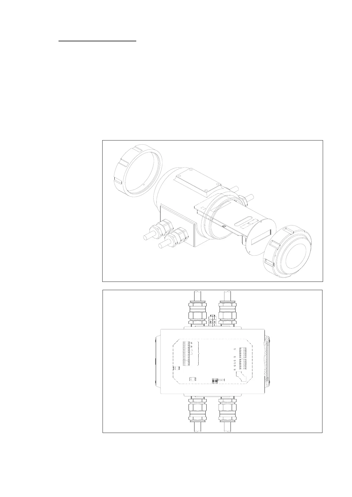
3-2 : Ex d CE ATEX Version (Ex d IIC T6) – IP 67: > See also NT 219-B
- The keypad keys have the same functions as for the industrial version.
- The two stuffing boxes on the porthole side are reserved for cables to the probes.
- To carry out the internal cabling of the probe cables on the MiniSonic card, it is necessary
to pull the support rack forwards: remove the three front panel screws.
- To comply better with EMC rules, stop and ensure the electrical connection of the cable
braids in the stuffing box housings.
- Once all the connections have been terminated and before closing up the unit, connect the
MiniSonic card to housing of the unit using the yellow / green wire at the rear.
- The unit must be grounded with respect to the external screw. Screw in and tighten the
covers (IP 67), then secure the removal-prevention screws before powering-up.
 Loading...