NT217 C GB1 11 / 27
RX 232
TX 232
- I s1
+ I s2
- I s2
+ I s1
V < 100 v
I < 0,1 A
P < 2 W
RS
+/-
-/+
12
I 2
13
14
MK4
TX 232
RX 232
Re1
I 1
Re2
Masse
BR5
1
2
+
-
1
2
3
4
6
7
8
9
10
11
5
2
1
1
2
3
4
5
6
RTX - 485
RTX + 485
BR2
BR1
SW
1 2 3 4
B R 3 B R 4
PT-GND1
PT-GND2
5
4
3
2
1
6
PT3
PT1
PT2
PT4
1
2
3
4
5
6
2
3
4
5
6
1
M
-
+
M
-
+
+
-
-
+
M
M
* Wiring for active output
+ I S2
+ I S1
- I S1
- I S2
BR2
2
11
10
9
8
7
6
5
4
3
14
13
12
BR5
2
1
-
+
1
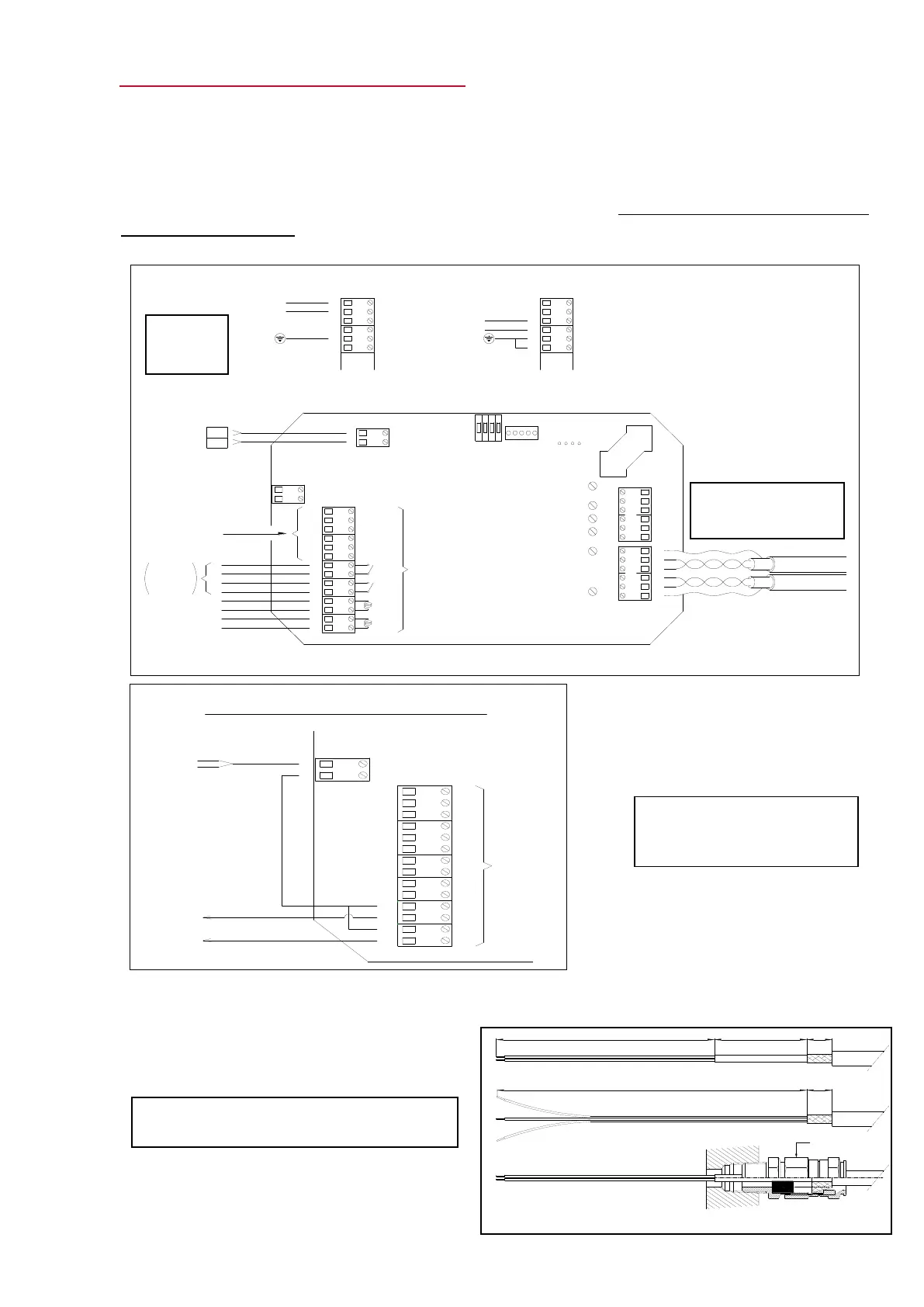
4 – MINISONIC 600 & 2000 WIRING PLAN: (Low Voltage Supply)
If the GP 01 Module for 90 to 230 V AC Supply is installed, see also NT 218
- Internal cables must be kept as short as possible. Cables are to enter through the stuffing
box facing the terminals.
- For the Ex d unit, imagine the card turned over with access from underneath.
- Plug-in connectors assist with cabling and maintenance. Choose flexible cables with a
limited cross-section (1.5 mm2) to facilitate these operations.
Ex d Version : Cables preparation ( to probes )
Upstream = 1,2,3
Downstream= 4,5,6
You can also wire the two
threads on BR5 N°2 to have the
(-) as the common line.
 Loading...