SonixTouch Service Manual 00.053.058, Revision D Chapter 7: Field Service Components
7-19
5. Using the 7mm wrench, undo the nut and washer securing the ground wire from the modulo to the LCD display
and, if applicable, to the ECG (refer to image in step 4).
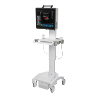
6. Disconnect the three (3) (bottom left rear) power cables connected to the modulo: LCD display power cable
(1), UPS input power cable (2) and UPS output power cable (3).
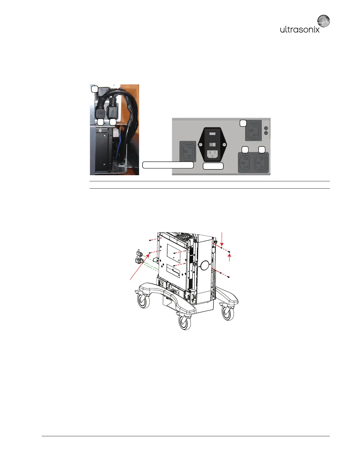
7. Using the 4mm Allen key, undo the two (2) screws and washers securing the modulo to the front of the system
frame.
8. Using the #2 Phillips screwdriver, undo the four (4) screws securing the modulo to the side of the system
frame.
9. Pull the modulo out of the system frame, then lift it clear.
Note: The LCD display power cable (1) is color coded with green tape.
System Power Connection
EMI Filter
1
2 3
1
2 3
M4x8 Pan Head Screw (x4)
Tool: #2 Phillips screwdriver
M5 Split Lock Washer (x2)
M5x12 Socket Head Screw (x2)
Tool: 4mm Allen key
 Loading...