SonixTouch Service Manual 00.053.058, Revision D Chapter 7: Field Service Components
7-21
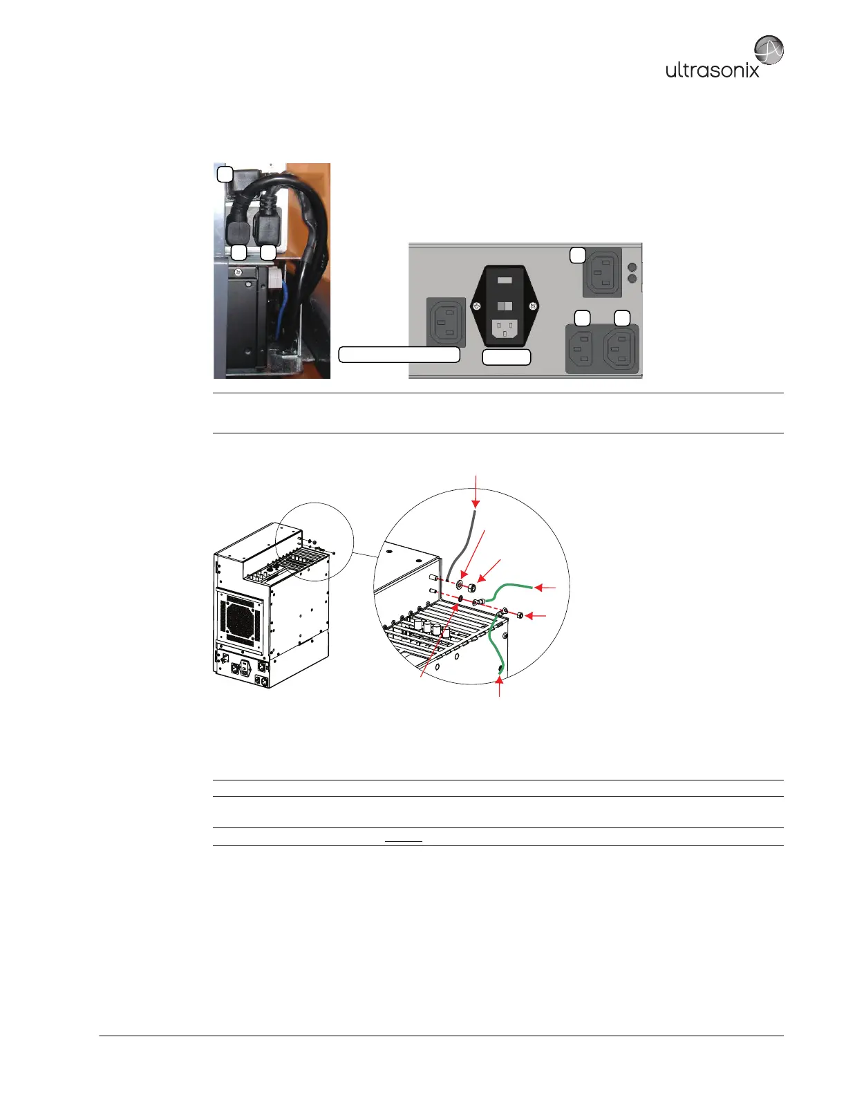
4. Connect the three (3) (bottom left rear) power cables connected to the modulo: LCD display power cable (1),
UPS input power cable (2) and UPS output power cable (3).
5. Using the 10mm wrench, fasten the washer and nut securing the ground mesh from the modulo to the console.
6. Using the 7mm wrench, fasten the washer and nut securing the ground wire from the modulo to the LCD
display and, if applicable, to the ECG (refer to image step 5).
7. Ensure all cables are properly connected to the System Case Connectivity Panel.
8. Test the modulo and UPS to ensure the system powers up and runs correctly (7.4.4).
9. Once the modulo and UPS test is successfully completed, use as many cable ties as necessary to neatly
fasten all cables, keeping them tucked out of the way.
10. Reinstall both side shrouds (7.3.2).
Note: The LCD display power cable (1) is color coded with green tape.
Once power cable 1 is connected, 2 and 3 will fit only in their designated connectors.
Note: Refer to 7.4.3 Connectivity to ensure the proper connections are made.
Note: If the system was ordered without
a UPS, test the modulo following the instructions in 7.4.5.
System Power Connection
EMI Filter
1
2 3
1
2 3
Ground mesh from console
M4 Nylock Nut
Tool: 7mm Socket wrench
M6 Nylock Nut
Tool: 10mm Socket wrench
M6 Flat Washer
External Tooth Lock Washer
Monitor Ground Wire
ECG Ground Cable (where applicable)
 Loading...