SonixTouch Service Manual 00.053.058, Revision D Chapter 7: Field Service Components
7-27
7.4.3.2 Back Connectivity Panel
The Back Connectivity Panel can be accessed from the rear of the system. The connectors are routed internally to
the system case connectivity panel which enables easy configuration.
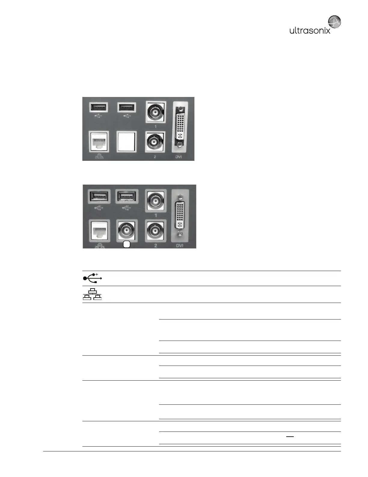
Figure 7-12: SonixTOUCH Back Connectivity Panel (A)
Figure 7-13: SonixTOUCH and SonixMDP/SP/OP Back Connectivity Panel (B)
Table 7-2: Back Connectivity Panels (A and B)
USB (x2)
Use to connect Ultrasonix-approved USB devices (e.g., printer, barcode reader,
memory stick, etc.).
LAN Use to connect the system to a network. This port supports 10Mb/100Mb.
1 BNC (Input) Connector
Connected to the console 1 button, use to connect an Ultrasonix-approved peripheral
(including a Footswitch).
Note: The device connected to this BNC is controlled by the settings configured for
the console (Custom) 1 button (refer to 6.1.3 to configure Custom Keys or to
Chapter 8 in the most recent User Manual).
If connection point 13 (Table 7-1) is in use, this will be an Output connection and
a Footswitch cannot be used.
2 BNC (Output) Connector
Connected to the console 2 button, use to connect an Ultrasonix-approved peripheral.
Note: The device connected here is controlled by the settings configured for Custom
Key 2 (6.1.3).
(3)
BNC (Output) Connector
(Back Connectivity
Panel B only)
Use to connect a non-USB Black & White (B&W) printer.
If this connector is used, it will be controlled by the console (Custom) 1 button and
BNC (Input) Connector (1) above, will be disabled.
Note: If this connector is in use a Footswitch cannot be connected.
This connector on Back Connectivity Panel B may or may not be labeled with the number 3.
DVI DVI Connector
Use to connect a second (DVI-compatible) LCD display.
Caution: This extra (DVI-compatible) LCD display may not be plugged into the
SonixTOUCH peripheral receptacle (Figure 3-5).
 Loading...