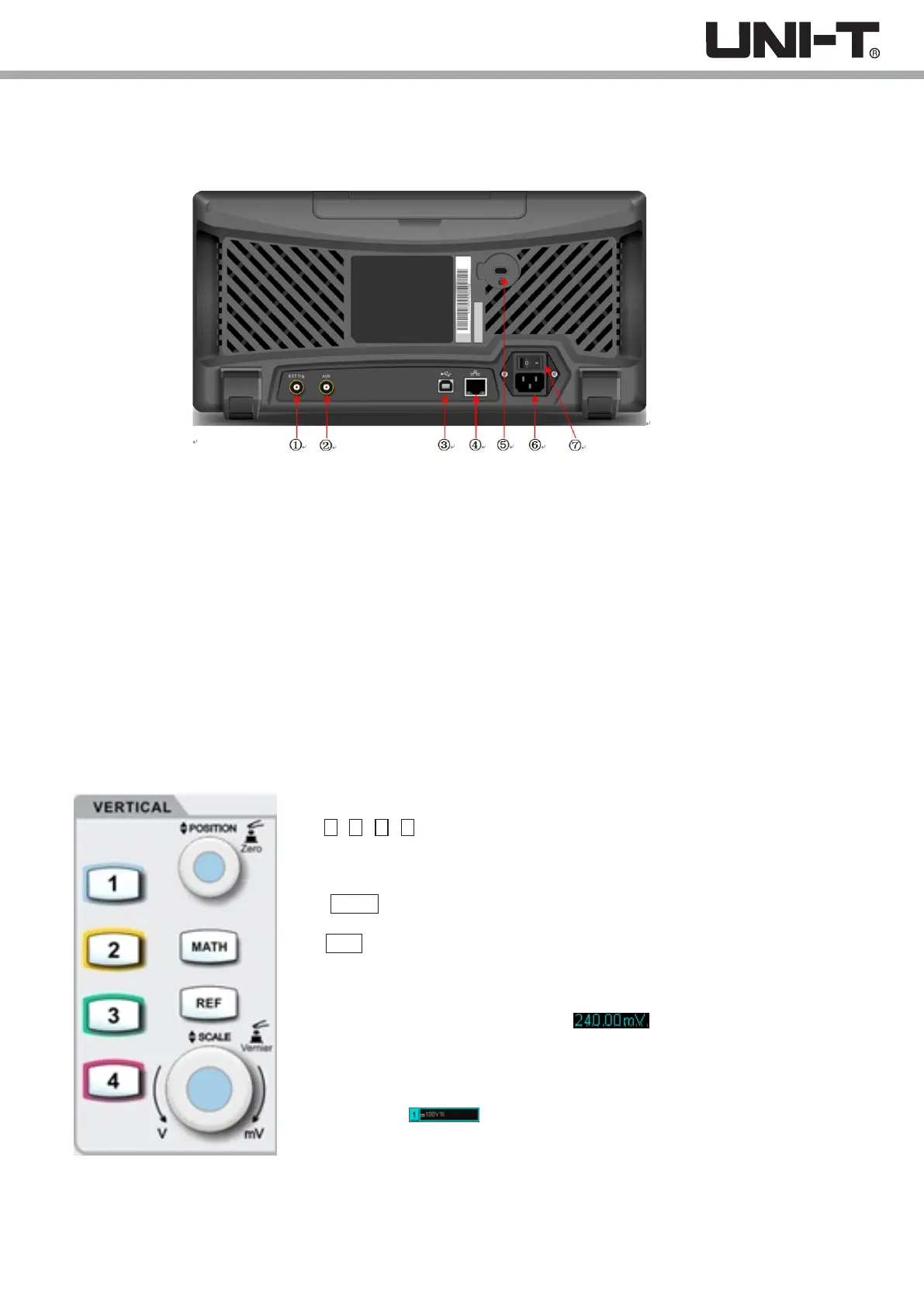
1.4 Rear Panel
Picture 1-4 Oscilloscope Rear Panel
①.EXT Trig: External trigger or external trigger/5 input
②. AUX: Pass/fail test output, also supports Trig_out output
③. USB Device: USB device interface, can be used to communicate with the PC
④. LAN: The oscilloscope can be connected to the LAN network for remote control
⑤. Safety Lock: Optional safety lock (sold separately) can be used for theft prevention
⑥. AC Power Socket: AC power terminal, power supply cord is provided within the accessory package
(100 ~ 240 V, 45 ~ 440Hz)
⑦. Power Switch: Main power switch, when turned on, press the power on/off button on front panel to turn on
the oscilloscope
(1) Vertical Control
①1 , 2 , 3 , 4 : Analog channel setting keys indicate CH1, CH2, CH3, and CH4,
which are identified by different colors also corresponding to the colors of
waveforms on the screen and channel input connectors. Press any key
to open the related channel menu (or activate and close the channel).
②MATH : Press this key to open the mathematical operation menu for add, subtract,
multiply, divide, FFT , logic, and advanced operations.
③ REF : Loads the previously stored reference waveform in the oscilloscope or the
USB disk, you can compare the currently measured waveform with the reference
waveform.
④ Vertical POSITION :Adjust the vertical position of the current channel waveform,
and display the vertical offset value at the baseline cursor. Press this
knob to return the channel display position back to the vertical midpoint.
⑤ Vertical SCALE : Adjust the vertical scale of the current channel. Turn clockwise to
reduce in scale and turn counterclockwise to increase in scale. The waveform
display amplitude will increase or decrease during the adjustment, and the scale
information at the bottom of the screen will change in real time.
The vertical scale has 1, 2, and 5 steps. Press the knob allows the vertical scale
adjustment to switch between coarse and fine tuning.
1.5 Operation Panels
11
 Loading...