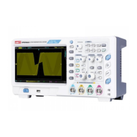
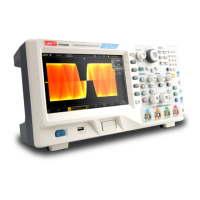
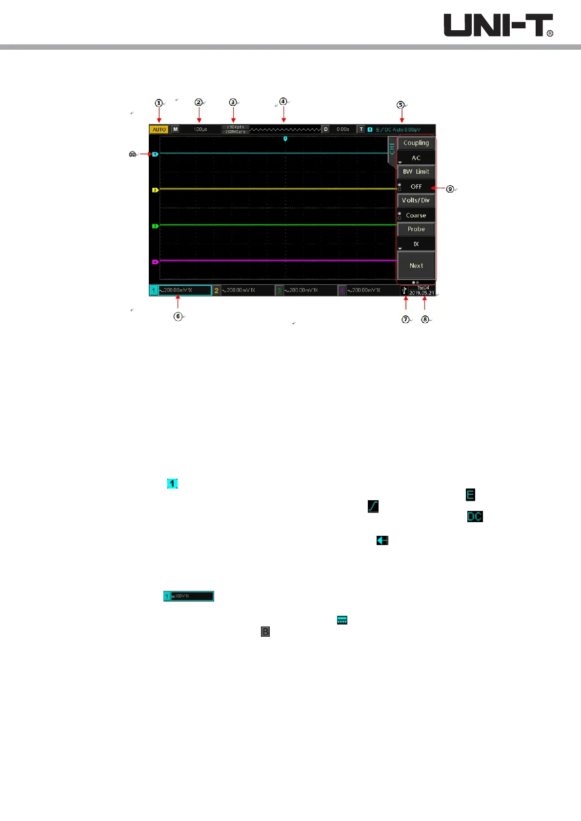
1.6 User Interface
Picture 1-5 Oscilloscope display interface
1.Trigger Status Identification: Include TRIGED, AUTO, READY, STOP, and ROLL.
2.Time Base Scale: Indicates the amount of time represented by one grid on the horizontal axis, which can be adjusted by
the horizontal SCALE knob.
3.Sampling Rate/Acquisition Mode: Indicates the current sampling rate and storage depth.
4.Horizontal Displacement: Shows the horizontal displacement, which can be adjusted by turning the horizontal POSITION
knob. Press in the knob returns the displacement back to 0.
5.Trigger Status: Displays trigger source, type, slope, coupling, level, etc.
a) Trigger Source: There are seven states: CH1~CH4, AC Line, EXT, and EXT/5. CH1~CH4 will each be of a different
trigger color. For example, is CH1.
b) Trigger Type: The types are edge, pulse width, video, slope, and advanced trigger. For example, is an edge trigger.
c) Trigger Edge: The types are rising, falling, and rising/falling. For example, is rising.
d) Trigger Coupling: The types are DC, AC, high frequency, low frequency and noise. For example, indicates DC
coupling.
e) Trigger Level: Indicates the current trigger level value, corresponding to the on the right side of the screen, can be
adjusted with the trigger level knob.
6.CH1 Vertical Identification: Displays CH1 activation state, channel coupling, bandwidth limit, vertical scale, and probe
attenuation coefficient.
a) Channel Activation State: The channel is activated when its color is consistent with the background color.
Press CH1~CH4 to open/close the corresponding channel.
b) Channel Coupling: Includes DC, AC, and grounding. For example, is DC coupling in CH1.
c) Bandwidth Limitation: Enable and there will be a icon shown on CH1 vertical status bar.
d) Vertical scale: When CH1 is activated, the vertical scale paraments can be adjusted with the SCALE knob in the vertical
control area.
e) Probe Attenuation Factor: Displays CH1 probe attenuation coefficient: 0.001X, 0.01X, 0.1X, 1X, 10X, 100X, and 1000X.
7.USB HOST Identification: Displays this indicator when the USB device is connected to a USB storage device such as a
USB flash disk.
8.Current date and time
9. Operation Menu: Displays the current operation menu. Press F1 ~ F5 can change corresponding submenu contents.
10.Analog Channels and Waveforms: Displays CH1~CH4 channels and waveforms, the channel indicator is consistent
with waveform color.
14
 Loading...