Note
l The test leads can add 0.1Ωto 0.2Ω of error to the
resistance measurement. To obtain precision
readings in low-resistance, that is the range of 200Ω,
short-circuit the input terminals beforehand and
record the reading obtained (called this reading as
X). (X) is the additional resistance from the test lead.
Then use the equation:
measured resistance value (Y) – (X) = precision
readings of resistance.
l When the resistance reading 0.5Ωin the short-circuit
condition, please check for loose test leads or other
reasons.
l For high resistance (>1MΩ), it is normal taking several
seconds to obtain a stable reading, and it is better to
choose shorter test lead.
l When there is no input, for example in open circuit
condition, the Meter displays “1”.
l When resistance measurement has been completed,
disconnect the connection between the testing leads
and the circuit under test.
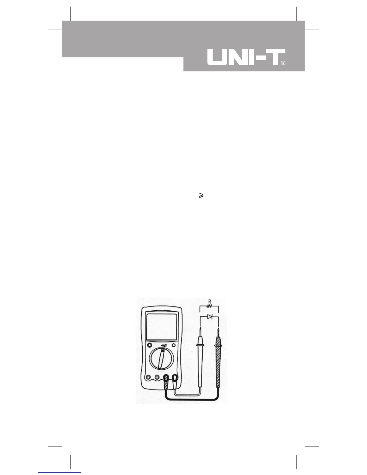
Measurement Operation(5)
D.Diode Testing (see figure 6)
(figure 6)
Model UT105: OPERATING MANUAL
21

 Loading...