Warning
To avoid possible damage to the Meter and to the
device under test, disconnect circuit power and
discharge all high-voltage capacitors before testing
diodes and continuity.
Never attempt an in-circuit current measurement
where the open circuit voltage between terminals
and ground is greater than 60V DC or 30V AC rms.
Measurement Operation(6)
Use the diode test to check diodes, transistors, and
other semiconductor devices. The diode test sends a
current through the semiconductor junction, then
measures the voltage drop across the junction. A good
silicon junction drops between 0.5V and 0.8V.
To test a diode out of a circuit, connect the Meter as
follows:
1. Insert the red test lead into the terminal and the
black test lead into the COM terminal.
2. Set the rotary switch to .
3. For forward voltage drop readings on any semiconductor
component, place the red test lead on the component’s
anode and place the black test lead on the component’s
cathode.
The measured value shows on the display.
Note
l In a circuit, a good diode should still produce a
forward voltage drop reading of 0.5V to 0.8V; however,
the reverse voltage drop reading can vary depending
on the resistance of other pathways between the probe
tips.
l Connect the test leads to the proper terminals as
said above to avoid error display.
l The open-circuit voltage is around 2.7V when testing
diode.
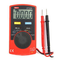
Model UT105: OPERATING MANUAL
22

 Loading...