34
Model UT106: OPERATING MANUAL
G. Voltage Drop Testing
Cut off the ignition system so as to disable the start
of the automobile.
Cut off the main ignition coil, shunt coil, cam and
starting sensor so as to cut off the ignition system.
Operate by reference to the automotive manual.
Set the rotary switch to 200mV or 2VDC. As prompted
at the LCD connect terminal, insert the red test lead
into the A terminal and the black test lead into the
COM terminal.
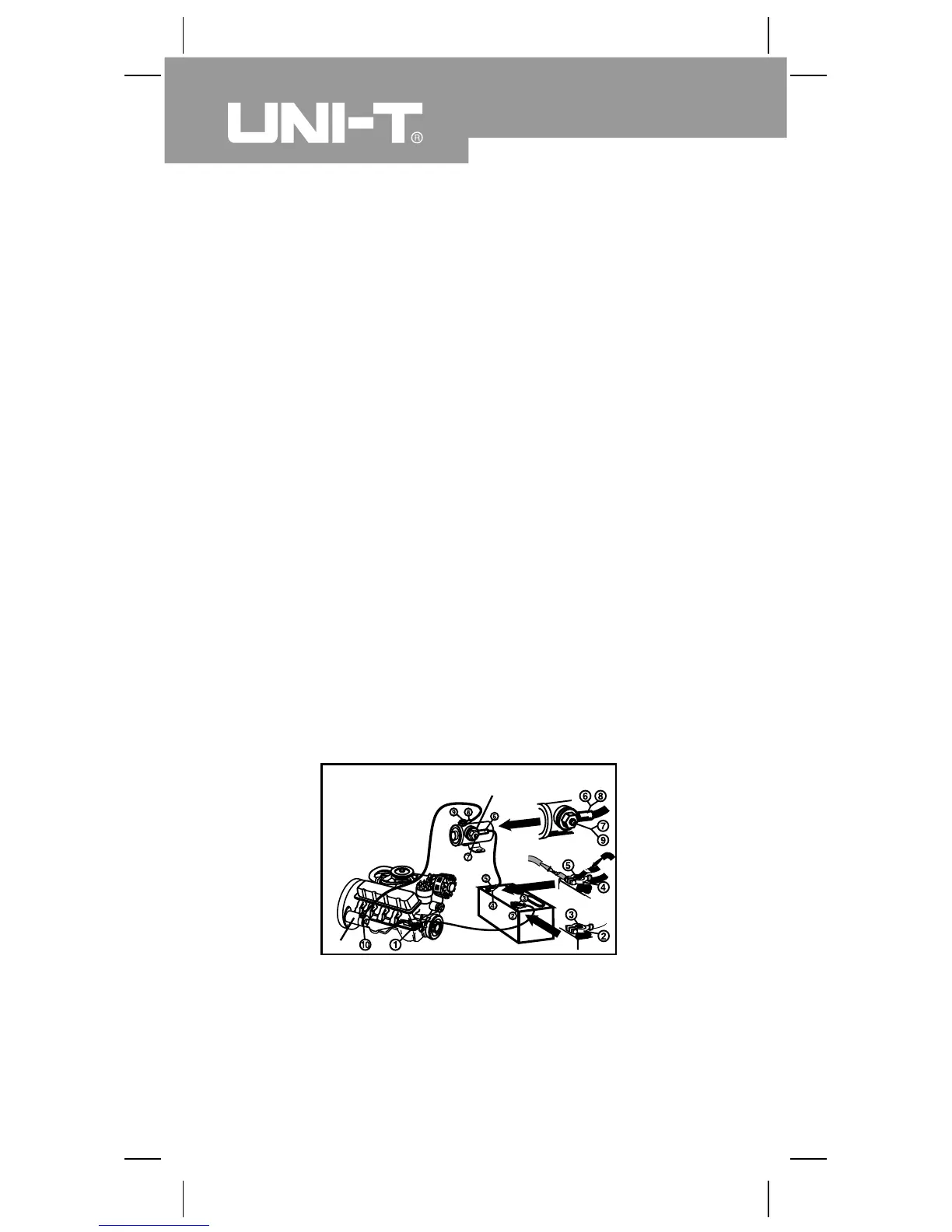
Refer to the LOSS typical trigger voltage circuit. (See
figure 12)
Test the voltage between any of the following pairs of
points respectively: 1&2, 2&3, 4&5, 5&6, 6&7, 7&8,
8&9, 8&10
1.
2.
3.
Test the voltage drops caused by the switch, cable,
solenoid or connector. Any abnormal voltage drop
generally results from an additional resistance. The
resistance will restrict the currents upon the start of the
engine, leading to the reduction of the load voltage of
the battery and the slow-down of the start of the engine.
Solenoid
Starter
LOSS Typical Trigger
Voltage Circuit
(figure 12)
Red
Black