UT219PV User Manual
15 / 27
1) Connect the red test lead to “V” terminal and black to “COM”.
2) Set the rotary switch to “ ”, short press the SELECT button to switch to VA or V+A function,
connect (in parallel) the test leads with the source or load to be measured, press and hold the
trigger to open the clamp jaws, clamp the conductor to be measured, then release the trigger
slowly to close the clamp jaws completely.
3) Read the measurement result from the LCD (Main display: DC power or voltage; Sub-display: DC
current).
Warning:
● Do not input voltage over 2500V DC. It is possible to measure higher voltage, but it may cause
damage to the Clamp Meter.
● For high voltage measurement, please pay special attention to avoid electric shock.
● If the measured voltage is ≥30V (AC/DC), the high-voltage warning symbol “ ” will be displayed.
“OL” will appear on the LCD if the measured voltage is >2510V DC and <-2510V DC.
● The power range is switched using the voltage range.
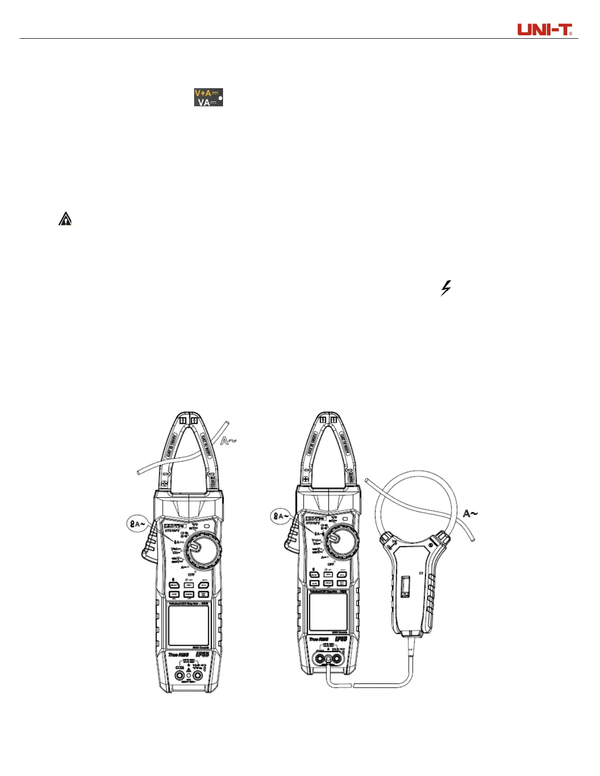
4. AC current measurement (Clamp jaws and flex current sensor) (Figure 8 & Figure 9)
Figure 8 Figure 9
 Loading...