1.2.2Boot Check
Press the soft power button and the light should change to yellow. The
oscilloscope then will show a boot animation, and it will enter the normal
interface afterwards.
1.2.3Basic Function Check
After the oscilloscope enters the normal interface, find the button at the
bottom right of the operation panel. Long press button to hear the voice
of the relay switch, and then press the button, the screen will automatically
complete the signal condition, 1kHz ,3Vpp square wave signal appears on
the screen . Press the key again, then the internal reference input is
disconnected, the channel can be in a normal external input state.
1.2.4Probe Compensation
When the probe is connected to any input channel for the first time, this step
might be required in order to match the probe and the input channel. Please
follow the following steps:
① Set the attenuation coefficient in the probe menu and the switch on the
probe to 10x, and connect the probe to CH1. Make sure the probe’s c
onnector is properly connected with the oscilloscope. Connect the probe’s
main clip and ground clip to the oscilloscope’s calibration and ground
terminal respectively. Open CH1 and press the button.
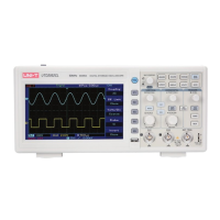
② Observed waveforms
Excessive Compensation Correct Compensation Insufficient Compensation
③ If the displayed waveform does not look like the above “correct
compensation” waveform, use a non-metallic screwdriver to adjust the
probe’s variable capacitance until the display matches the "correct
compensation" waveform.
Warning: To avoid electric shock when measuring high voltage using the
probe, please ensure that the probe insulation is in good condition and avoid
physical contact with any metallic part of the probe.
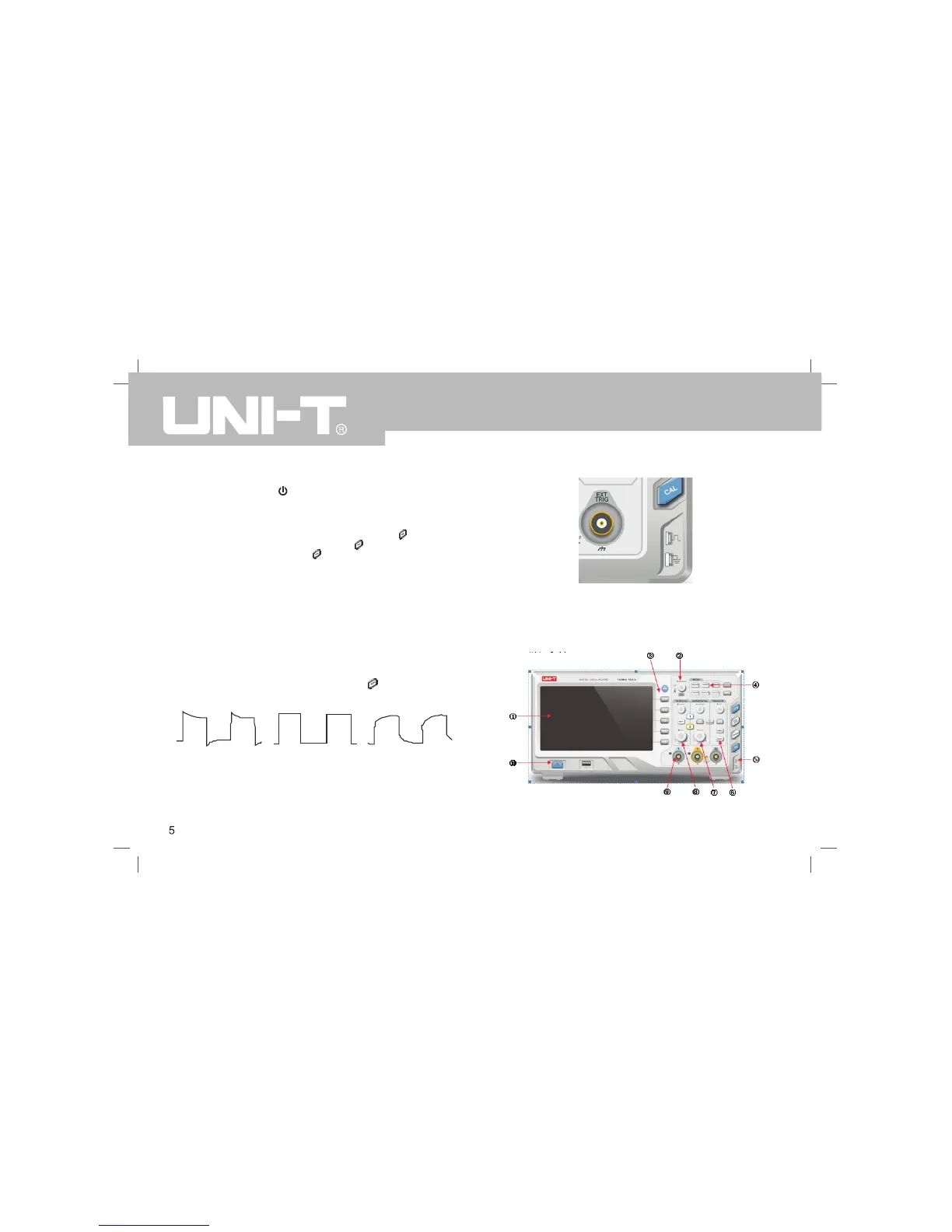
1.3Front panel introduction
Front panel
UTD2000CEX-II User Manual
 Loading...