①.Screen display area
②. Multifunction knob
③. Function menu key
④. Control menu softkey.
⑤. Probe compensation signal connecting piece and grounding
⑥. Trigger control area.
⑦. Horizontal control area.
⑧. Vertical control area.
⑨. Analog channel input.
⑩. Power soft key
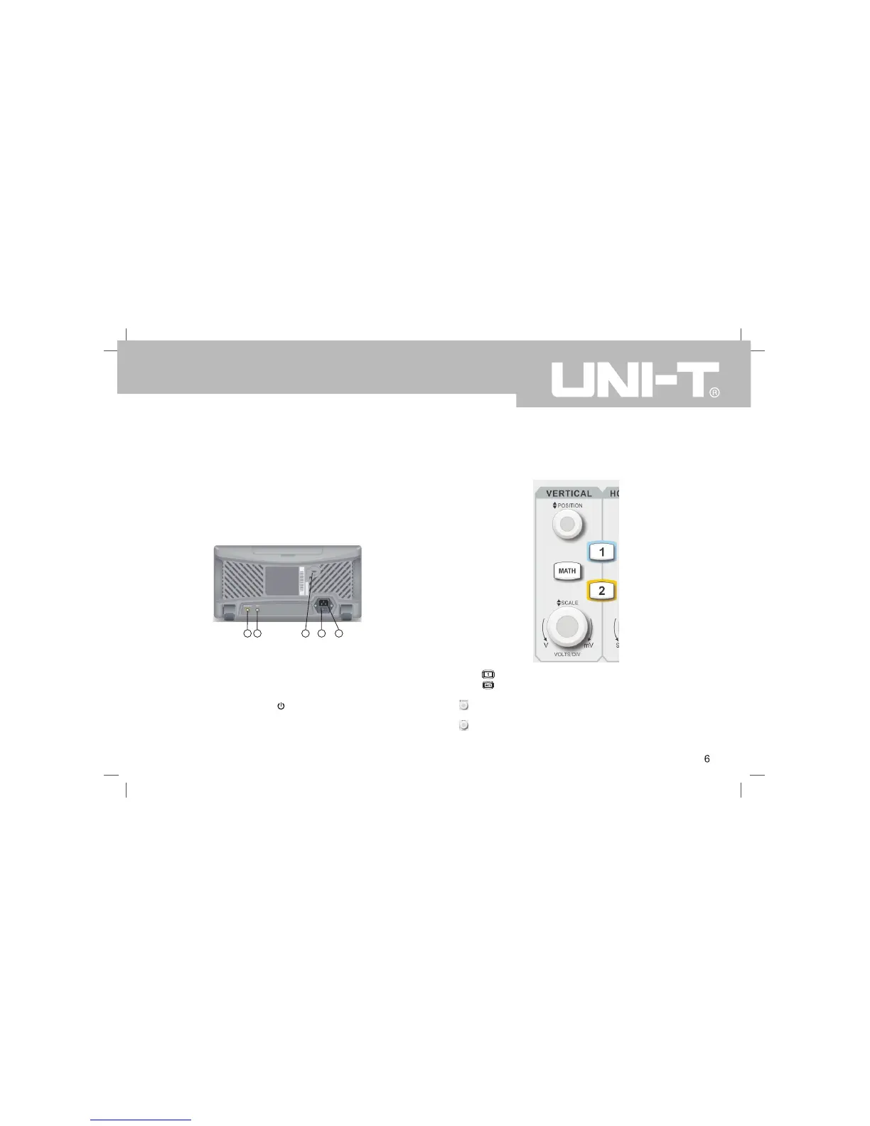
1.4 Back panel introduction
1 2
3
4
5
Back panel
①.Pass/Fail:Pass/fail test output, also supports Trig_out output
②. AWG:This model does not support
③. Security lock: you can use the security lock (sold separately)
Oscilloscope can be locked in a fixed position through the key hole .
④. Power Switch: after the AC socket is connected to the power supply, turn
on the Power Switch. Press the button on the front panel to Power On.
⑤. AC power input socket : AC power input port . Use the power cord supplied
within the accessory package to connect the oscilloscope to the AC power
supply (the power supply for the oscilloscope to require is 100 to 240 V,
50Hz/60Hz).
1.5 Operation Panels
This section describes the front panel operations to help users to quickly
familiarize with the UTD2000CEX-II series.
(1)Vertical Control
①.Press buttom to open or close the two channels display.
②. Press buttom to open the mathematical operations menu for add,
subtract, multiply, divide, FFT, filtering, logic, and advanced operations.
③. Vertical Position Knob: Used to adjust the vertical position of the current
channel waveform.
④. Vertical Scale Knob: Used to adjust the vertical scale of the current
waveform. The vertical scale has 1, 2, and 5 steps.
UTD2000CEX-II User Manual

 Loading...