EasyManuals Logo

Unimax MA-2025 User Manual

Unimax MA-2025
75 pages
To Next Page IconTo Next Page
To Previous Page IconTo Previous Page
Page #12 background imageLoading...
Page #12 background image
12
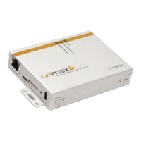
2.2 Side Panel (Left)
1. Ethernet Port
2. Diagnostic Port (for debugging)
3. Digital I/O (Input: max 5VDC, Output: max 3.3VDC)
PIN NUMBER
DESCRIPTION
1 (VDD)
3.3V out
2 (D/I 1)
Digital input (max 5VDC)
3 (D/I 2)
Digital input (max 5VDC)
4 (D/O 1)
Digital output (max 3.3VDC)
5 (D/O 2)
Digital output (max 3.3VDC)
6 (GND)
GND
[Table 2: Digital I/O PIN Number]
4. Reset (Factory Reset)
5. Power (9 30VDC)
2.3 Side Panel (Right)
3G FME Male Antenna Connector
2.4 Back Panel
SIM Connector

Table of Contents

Questions and Answers:

Question and Answer IconNeed help?

Do you have a question about the Unimax MA-2025 and is the answer not in the manual?

Unimax MA-2025 Specifications

General IconGeneral
BrandUnimax
ModelMA-2025
CategoryNetwork Router
LanguageEnglish

Related product manuals