J
jacksonspencerAug 3, 2025
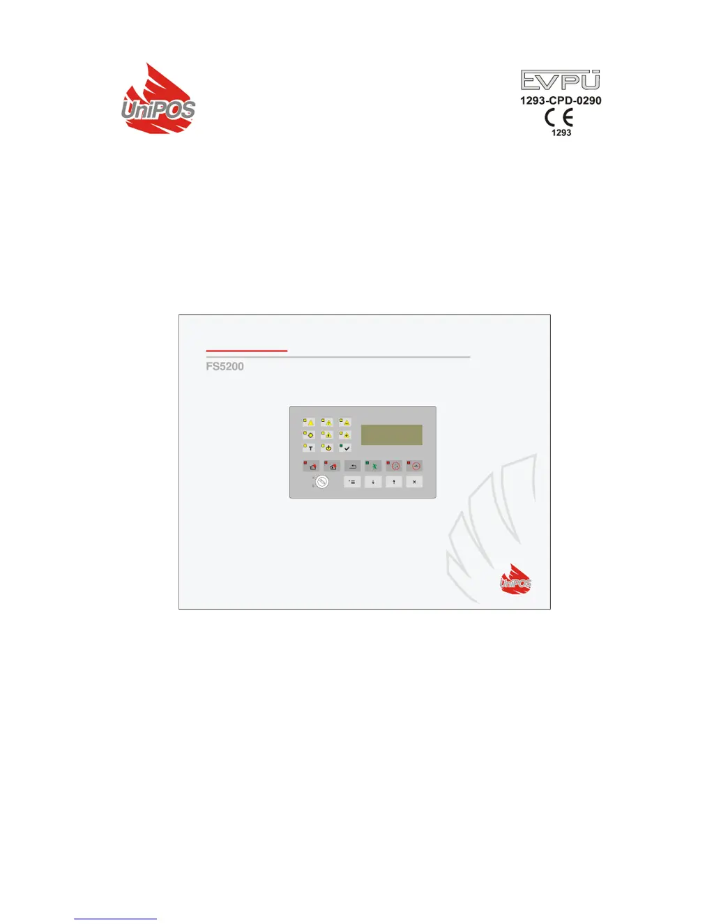
What to do if there is a fault in the mains power supply of my UniPOS FS5200?
- MMelissa MejiaAug 3, 2025
If your UniPOS Control Panel indicates a fault in the mains power supply, first, try to restore the mains power. If the issue continues, replace the burnt fuse Fu1 – 4A.