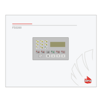
UniPOS Fire Control Panel FS5200
Instruction manual Page 7
Revision 8/07.17 of 69
PROCEEDING FROM FIRE CONDITION STAGE I TO FIRE CONDITION STAGE II – the time is
user defined for each fire alarm line separately. During the phase Fire condition stage I the remaining
time for the selected fire alarm line is indicated on the LCD display. During the remaining time actions
can be taken, for example press or .
RELAY OUTPUT – relay, potential free, switching outputs that control external executive devices.
REMOVED FIRE DETECTOR – non-system non-fatal fault condition due to removed fire detector
in a line. To use this function, the fire detectors shall be connected as in Appendix 5 a.
SHORT CIRCUIT IN A LINE OR IN A CONTROLLABLE OUTPUT – non-system non-fatal fault
condition due to registered current value in a line or in a controllable output that exceeds a specified
threshold value. The threshold value for each line shall be user defined.
SUPRESSED OUTPUT – controllable or relay output which should normally be activated (the fire
alarm line is in the relevant phase Fire condition) but is manually switched off by the user.
SYSTEM FAULT – fatal fault condition due to a fault in a basic component of the fire control panel
(or system). The System fault may be a fatal error or a non-fatal error. The event is indicated by
common light indicators, local sound signaling and a text message displayed on the LCD display.
SYSTEM OPERATION – the fire control panel executes internal operations to set its registers.
This is visualized on the LCD display with a text message for system operations, before the user is
allowed to proceed with his work with FS 5200.
3. Function
Fire control panel FS5200 is designed to operate with conventional automatic fire detectors and
manual call points. The panel has outputs provided for external executive devices. Its modular
structure allows for variable configurations according the specific features of the protected site
4. Technical data
4.1. Modules
4.1.1. Type of modules
Basic module
Additional module
Power supply module
4.1.2. Basic module
Basic module
(Circuit Board 5200Basic and 5200Indication) - 1 controllable output
- 2 relay outputs for fire condition
- 1 relay output for fault conditions
Expansion
Module 5201 - 8 lines
Module 5203 - 8 relay outputs for fire condition
Module 5204 - 16 relay outputs for fire condition
Note: The Basic Module can not be expanded with Module 5203 and Module 5204 at the same
time – you may insert only one of them.
4.1.3. Additional module
Module 5202 - 8 lines
- 1 controllable output
Expansion
Module 5201 - 8 lines
 Loading...