Page 27
POWERING TECHNOLOGY
Manual No. aspiro2u-3
aspiro2u_m23-man-rev3-0516.indd
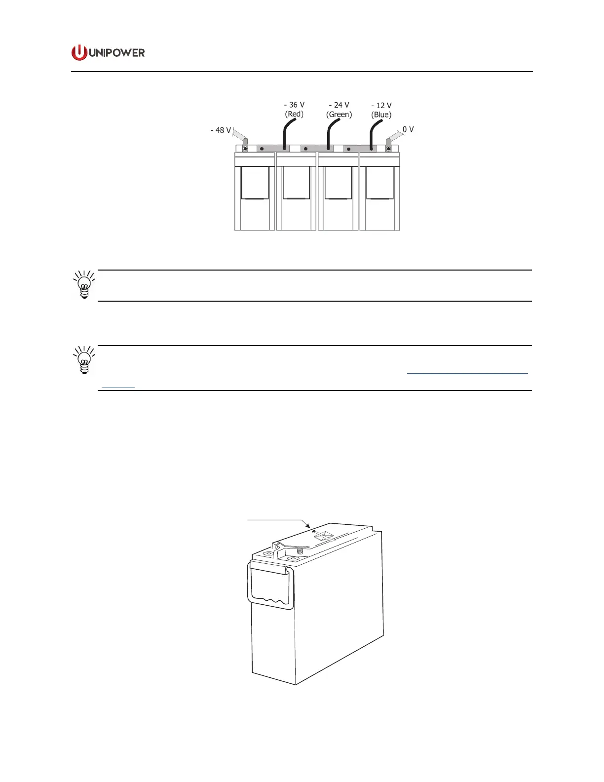
Figure 4-12 4-Block Symmetry Measurement (for illustration only)
NOTE The interblock Connection Kit is not delivered with the system.
4.11 Temperature Sensor Connection
NOTE The power system is usually delivered with pre-connected temperature sensor
cables. If not, use a three-pin plug and connect according to the Appendix A - Installation
Details.
Battery Temperature
Temperature sensor 1 measures the temperature of the battery bank while the controller
adjusts the oat charge voltage according to the temperature compensation factor set in the
controller. This factor must be set in the controller according to the battery manufacturer ‘s
recommendations.
Fasten the temperature sensor in the middle of the battery bank, Figure 4-13.
Figure 4-13 Temperature Sensor Connection
 Loading...