Page 35
POWERING TECHNOLOGY
Manual No. aspiro2u-3
aspiro2u_m23-man-rev3-0516.indd
Chapter 6 Maintenance & Troubleshooting
6.1 Maintenance
6.1.1 Checking Terminal Connection
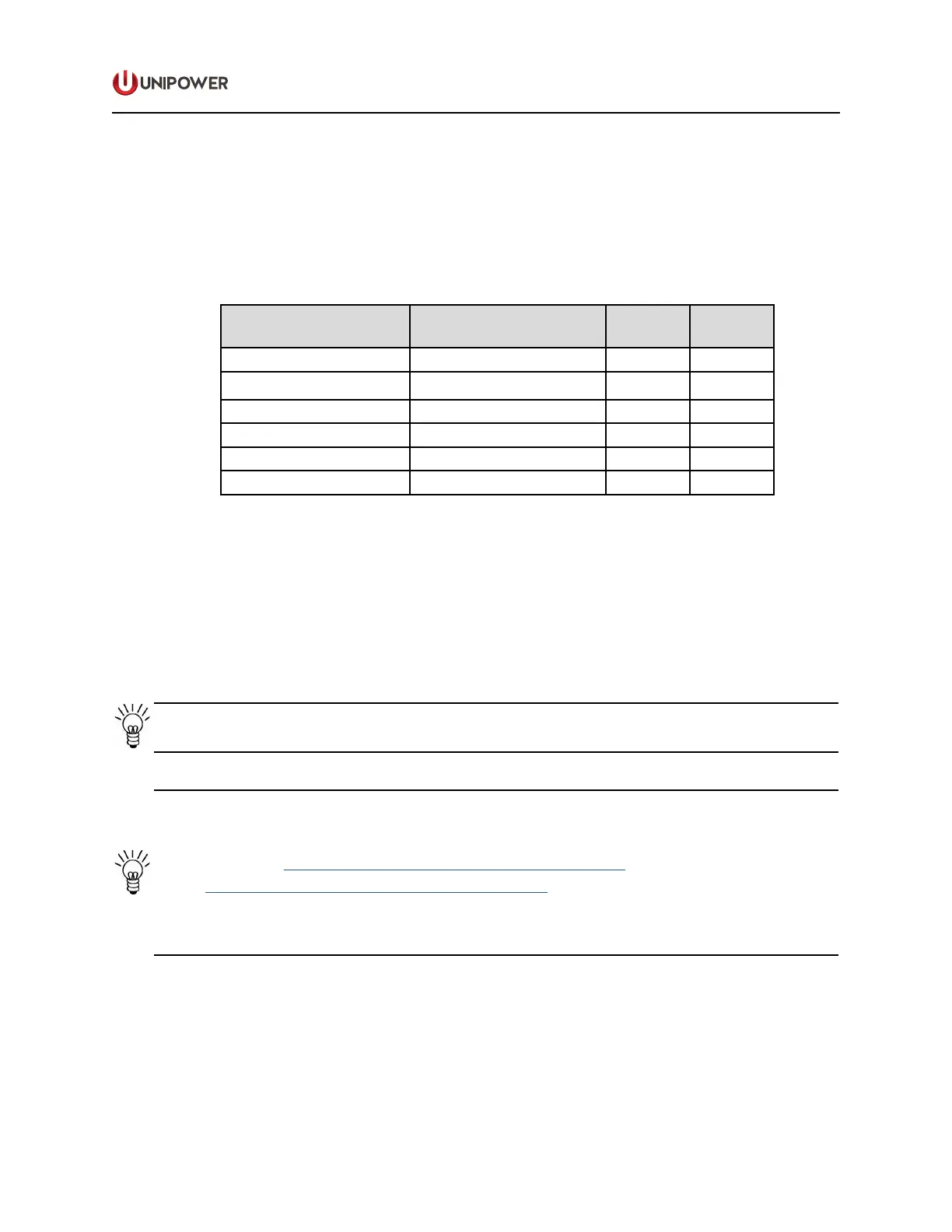
The connections on the terminal blocks and circuit breakers must be checked according to
the Table 6-1 at least once a year.
TYPE OF CONNECTION MODEL / DESCRIPTION TORQUE
(Nm)
TORQUE
(Inch LB)
0 V Load AKG 5AWG/16mm² 2.5 22
0 V Battery AKG 2AWG/35mm² 3.5 31
(-) Battery Terminal Screw M6 4 35
Signals Phoenix Mini Combicon 0.25 2
AC Input UK10 / UKLKG10 1.5-1.8 13-16
SPD Terminal Screw M5 4.5 40
Table 6-1 Connection Torque Setting Check
6.2 Troubleshooting
This troubleshooting chapter helps to determine the cause of the problem and suggests
possible repair solutions. If the rst step of the recommendation does not solve the problem
continue to the next one.
NOTE If the malfunctioning of the system persists, please contact UNIPOWER technical
support.
NOTE For a description of Alarms and Messages generated by the system controller see
the Alarms/Messages section of the appropriate controller manual:
ACC Extended: http://www.unipowerco.com/pdf/acc-man.pdf
PCC: http://www.unipowerco.com/pdf/pcc-man.pdf
By default, alarms are set to be indicated with a red light (higher priority) and messages
with a yellow light (lower priority).
 Loading...