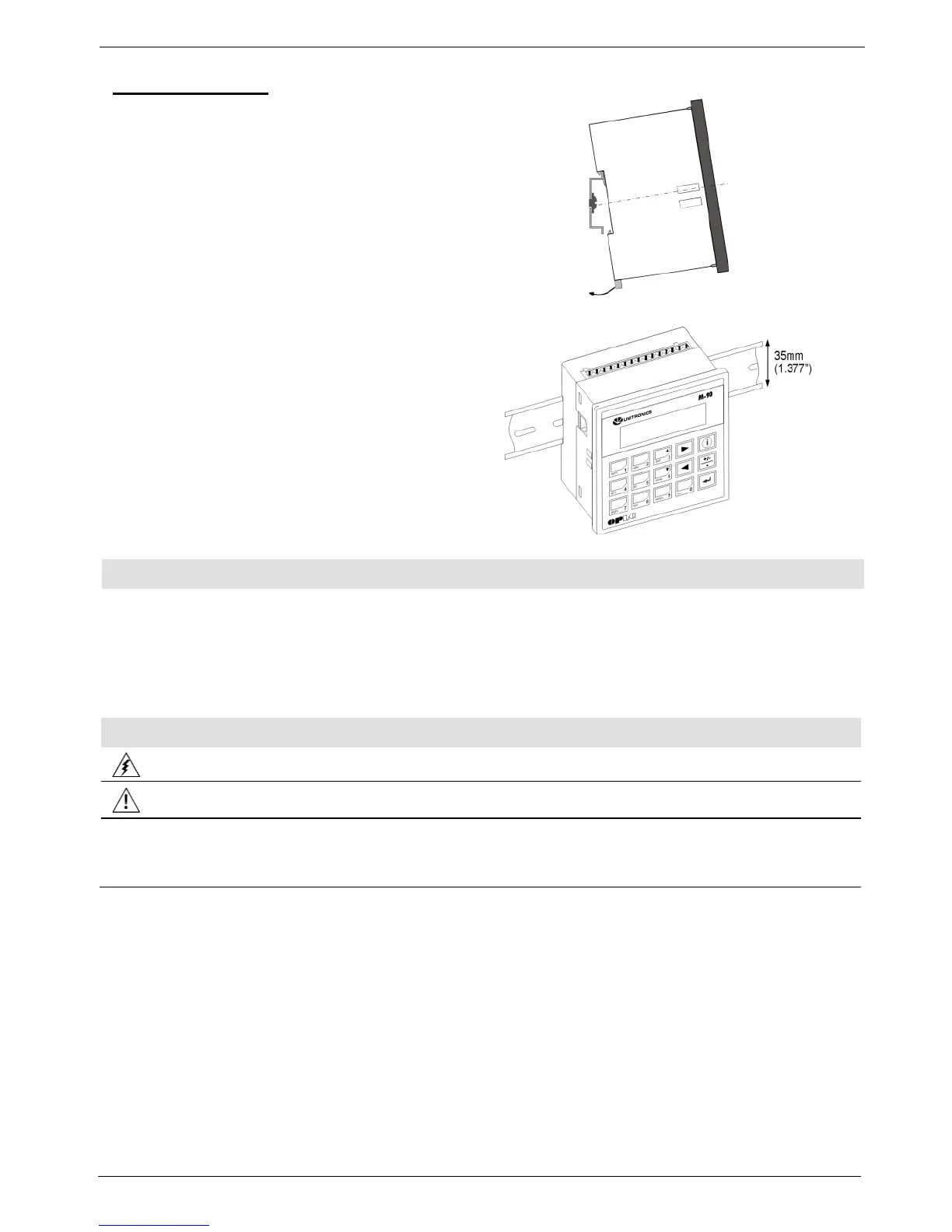
1. Snap the controller onto the DIN rail
as shown in the figure to the right.
2. When properly mounted, the controller
is squarely situated on the DIN-rail as
shown in the figure to the right.
The controllers offer an on-board I/O configuration that differs according to the controller model; I/O
wiring diagrams are in the controller’s technical specification sheet.
Additional I/Os may be integrated into the system via I/O Expansion Modules that you plug into the
controller’s I/O expansion port. Note that the relevant wiring diagrams are in the module’s technical
specification sheet, and that an I/O adapter is required for most modules.
Do not touch live wires.
Unused pins should not be connected. Ignoring this directive may damage the device.
To avoid damaging the wire, do not exceed a maximum torque of 0.5 N·m (5 kgf·cm).
Do not use tin, solder, or any substance on stripped wire that might cause the wire
strand to break.
Use crimp terminals for wiring; use 26-14 AWG wire (0.13 mm
2
–2.08 mm
2
).
1. Strip the wire to a length of 7±0.5mm (0.250–0.300”).
2. Unscrew the terminal to its widest position before inserting a wire.
3. Insert the wire completely into the terminal to ensure a proper connection.
4. Tighten enough to keep the wire from pulling free.