The pinouts below show the signals between the adapter and port.
*Standard programming cables do not provide connection points for pins 1 and 6.
M91 only: RS232 to RS485: Changing Jumper Settings
To access the jumpers, open the controller and then remove the module’s PCB board.
Before you begin, turn off the power supply, disconnect and dismount the controller.
When a port is adapted to RS485, Pin 1 (DTR) is used for signal A, and Pin 6 (DSR)
signal is used for signal B.
If a port is set to RS485, and flow signals DTR and DSR are not used, the port can also
be used to communicate via RS232; with the appropriate cables and wiring.
Before performing these actions, touch a grounded object to discharge any electrostatic
charge.
Avoid touching the PCB board directly. Hold the PCB board by its connectors.
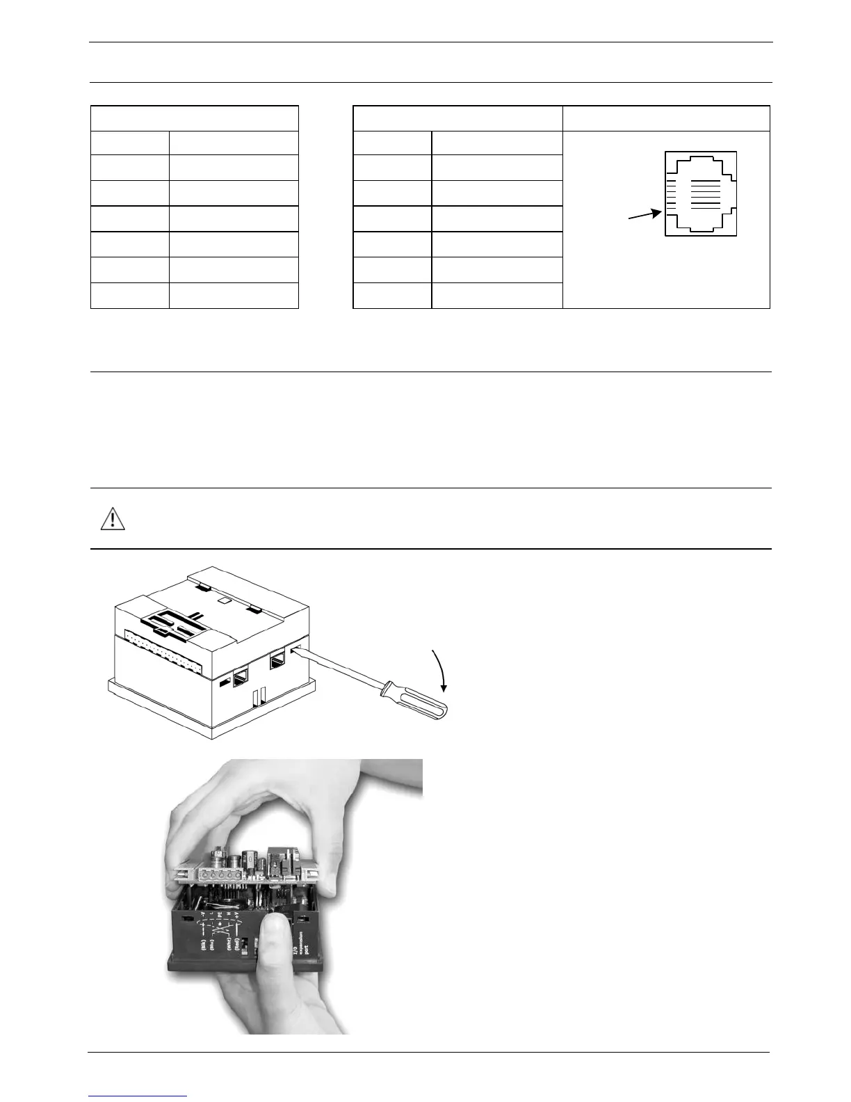
1. Turn power off before opening the
controller.
2. Locate the 4 slots on the sides of the
controller.
3. Using the blade of a flat-bladed
screwdriver, gently pry off the back of
the controller.
4. Gently remove the top PCB board:
a. Use one hand to hold the top-most
PCB board by its top and bottom
connectors.
b. With the other hand, grasp the
controller, while keeping hold of the
serial ports; this will keep the
bottom board from being removed
together with the top board.
c. Steadily pull the top board off.
5. Locate the jumpers, and then change
the jumper settings as required.
Jumper settings are shown on
page 7.